Here’s a step-by-step guide to simulating a composite wing panel structural model in Abaqus, including geometry creation, material definition, layup setup, loading, and analysis.. Wing panels are critical parts of an aircraft’s wing, designed to withstand aerodynamic forces, fuel loads, and inertial loads while maintaining aerodynamic efficiency. Here’s a detailed breakdown of what a wing panel structural model entails:
1. Key Components of a Wing Panel Structural Model
- Skin Panels:
- The outer surface of the wing, typically made of aluminum alloys, composites, or hybrid materials.
- Transfers aerodynamic loads (pressure, shear) to the underlying structure.
- Spars and Ribs:
- Spars: Long, beam-like structures running spanwise (front to rear) that carry bending and torsional loads.
- Ribs: Vertical or curved elements running chordwise (leading to trailing edge) that maintain the wing’s shape and distribute loads.
- Stringers/Stiffeners:
- Longitudinal reinforcements attached to the skin to prevent buckling and increase stiffness.
- Fasteners and Joints:
- Rivets, bolts, or bonded joints connecting the skin to spars, ribs, and stringers.
- Fuel Tanks (if applicable):
- Integrated into the wing structure in many aircraft, adding mass and pressure loads.
2. Modeling Approach
A wing panel structural model is typically created using Finite Element Analysis (FEA) software (e.g., Abaqus, ANSYS, NASTRAN) and includes:
a. Geometry
- CAD Representation: 3D geometry of the wing panel, spars, ribs, and stringers.
- Simplifications: Use of shells or 2D elements for thin skins and beams for spars/stringers.
b. Material Properties
- Metals (Aluminum/Titanium): Linear elastic or elastic-plastic models.
- Composites (CFRP/GFRP): Orthotropic properties with ply-by-ply layup definitions (e.g., [0°/45°/90°/−45°]).
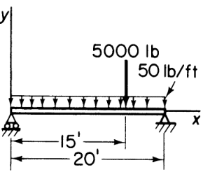
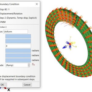
c. Loads and Boundary Conditions
- Aerodynamic Loads: Distributed pressure from airflow (lift, drag).
- Inertial Loads: Due to aircraft maneuvers (e.g., n⋅g, where n=load factor).
- Fuel Pressure: Hydrostatic pressure in fuel tanks.
- Boundary Conditions: Fixed or constrained connections to the fuselage or adjacent wing sections.
d. Contact and Fastener Modeling
- Riveted Joints: Modeled as rigid links or connector elements.
- Bonded Joints: Simulated using cohesive zone models (CZMs) or adhesive elements.
3. Types of Analysis
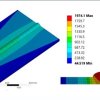
- Static Analysis:
- Assess stress, strain, and deformation under steady loads (e.g., cruise condition).
- Dynamic Analysis:
- Study vibration modes (natural frequencies) and response to gusts or turbulence.
- Buckling Analysis:
- Predict critical buckling loads for thin-skinned panels under compressive loads.
- Fatigue Analysis:
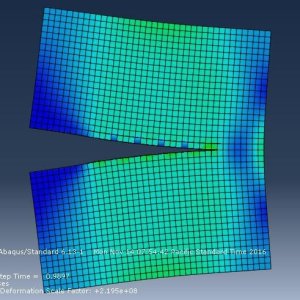
- Evaluate crack initiation/propagation due to cyclic loads (e.g., pressurization cycles).
- Damage Tolerance Analysis:
- Simulate the impact of defects (e.g., cracks, delamination in composites).
Simulation in Abaqus
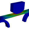
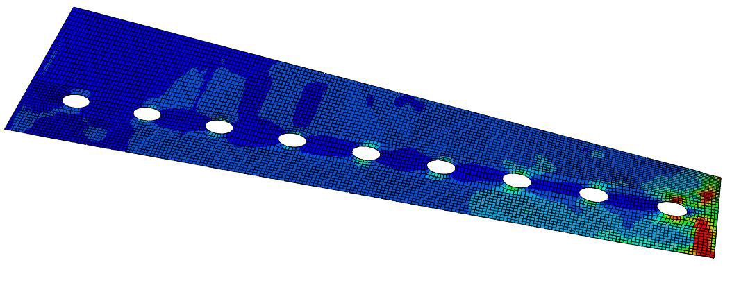
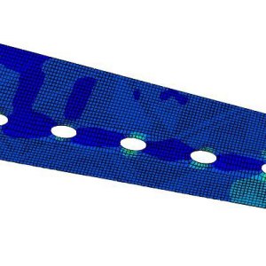
In this tutorial, you will modify a structural model of a composite wing panel to define the material properties including the ply failure parameters in Abaqus software. You will then perform a static analysis and visualize the simulation of the damage propagation with Abaqus/Viewer.
When you complete this tutorial, you will be able to:
– Define the material properties of a composite ply
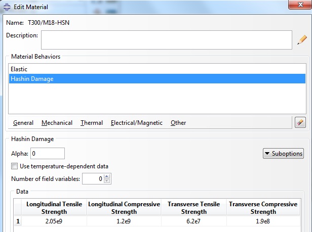
– Define the coefficients of Hashin’s failure criteria
– Define a damage propagation model
– Use the visualization module to create ply stack plots and contour plots on different plies
Preliminaries
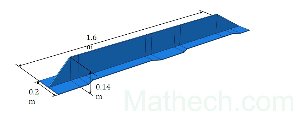
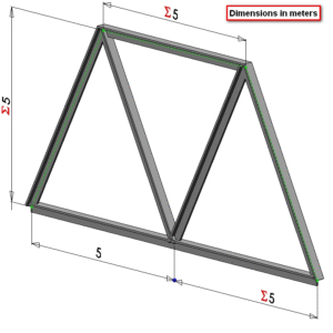
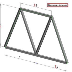
The wing model is composed of:
– a cover
• Dimensions: 19.5 m x 5 m, 6 mm thick
• Material: UD carbon / epoxy T300/M18

Setting up the composite plate model in Abaqus
Open the model Tutorial11a.cae.
This file contains the geometry, the lay-up definition and the mesh of the different components, the assembly, the boundary conditions and the loading. The units are: m and Pa.
In this tutorial, you will modify the material properties of the skin to include the Hashin’s failure criteria and the progressive damage models. You will then run a static analysis and use the visualization module to post-process the results of the simulation.
In the Edit Material dialog box, from the material editor’s menu bar, select Mechanical → Damage for Fiber-Reinforced Composites → Hashin Damage. Enter the material data in Abaqus
To read more setting options, Download composite wing panel in Abaqus file.
Composite Layup Manager
Define the maximum degradation and element removal option.
Go into the Mesh Module and click the Assign Element Type icon
Read about Composite 4-layer plate simulation in Abaqus


Reviews
There are no reviews yet.