
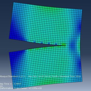
Crack propagation prediction helps engineers to optimize designs for enhanced durability and safety in real-world. In this post, we provides a step-by-step crack propagation analysis in a plate using Abaqus. The Extended Finite Element Method (XFEM) provides an efficient way to simulate crack growth without requiring frequent remeshing. This Feature making it ideal for modeling complex fracture behavior.
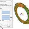
Problem definition for simulating crack in square plate
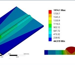
2D deformable shell (4 m × 4 m). With 1 m Crack length

Using XFEM within Abaqus, provides ability to simulate crack initiation and propagation under applied stresses and loads.
Whether you’re tackling fatigue analysis, structural integrity assessments, or damage tolerance studies, this guide provides suitable insights for fracture simulation and crack growth using XFEM.
You can Read about Crack propagation analysis here
You can Download Step-by-Step Crack propagation Analysis Abaqus CAE file for free
Pre Crack Analysis Setup in Abaqus
Material Properties (Aluminum)
- Young’s Modulus: 70 GPa
- Poisson’s Ratio: 0.33
- Density: 2700 kg/m³ (optional for static analysis)
- Damage Initiation:
- Criterion: Maximum Principal Stress (
MAXPS = 250 MPa, typical for aluminum).
- Criterion: Maximum Principal Stress (
- Damage Evolution:
- Type: Displacement-based softening.
- Displacement at Failure: 0.1 m (user-defined).
Abaqus Workflow for Crack Modeling
Step 1: Geometry & Assembly
- Part: Create a 2D deformable shell (4 m × 4 m).
- Crack: Define the initial crack as a partition (1 m long).
- Assembly: Position the plate in the global coordinate system.

Step 2: Material Assignment
– Defining Material Properties for crack propagation Analysis
To create material properties, enter the Property module, double-click on Material in the tree view, and proceed as follows.
Name: Aluminum, Mechanical:
Elasticity → Young’s Module: 70 × 109 ,Poisson’s Ratio: 0.33 → ok Elasticity → Damage for Traction Seperation Laws → Maxps Damage: 10
Click on the Damage Evolution suboption and enter a value of 0.1 for the change in position at the moment of damage. Then click OK twice to close the material Edit window.

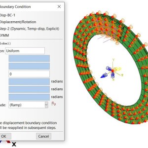
Step 3: Loads & Boundary Conditions for Crack propagation
- Pressure Load: Apply -5.5 MPa to the top edge.
- Boundary Conditions:
- Bottom Edge: Fully fixed (
U1=U2=UR3=0). - Sides: Allow vertical displacement only (
U1=0).
- Bottom Edge: Fully fixed (
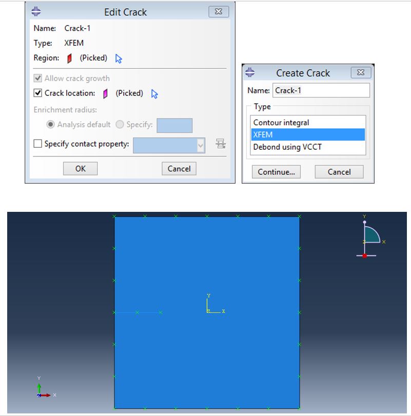
Step 4: XFEM Crack Definition in Abaqus
- Interaction Module:
- Go to Special > Crack > Create.
- Type: XFEM.
- Crack Domain: Select the plate.
- Enrichment Radius: 0.1 m (adjust based on mesh size).
- Initial Crack: Select the partitioned crack line.
Defining the contact between crack and geometry
Enter the Interaction environment and select special from the top menu and then crack and click on create to open the following window. In this window, select XFEM and continue. Select the square and in the opened window, check the location crack to activate the flash icon. Click on this icon and select the crack and then Done and then ok.
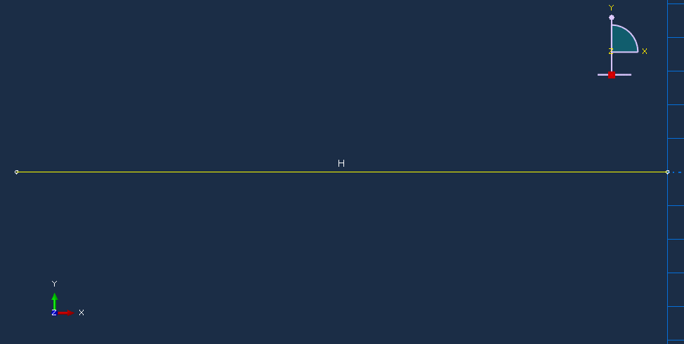
Step-5: Creating Geometry in Abaqus for Crack propagation analysis
To draw a track, enter the Part module and proceed as follows:
Create Part → Modeling Space: 2D, Type: Deformable, Base Feature: wire, Type: Planar, Approximate size: 2→ Continue
Click on the wire and enter the following coordinates. Then click the cross at the bottom of the page and Done.
(-2,0), (-1,0)
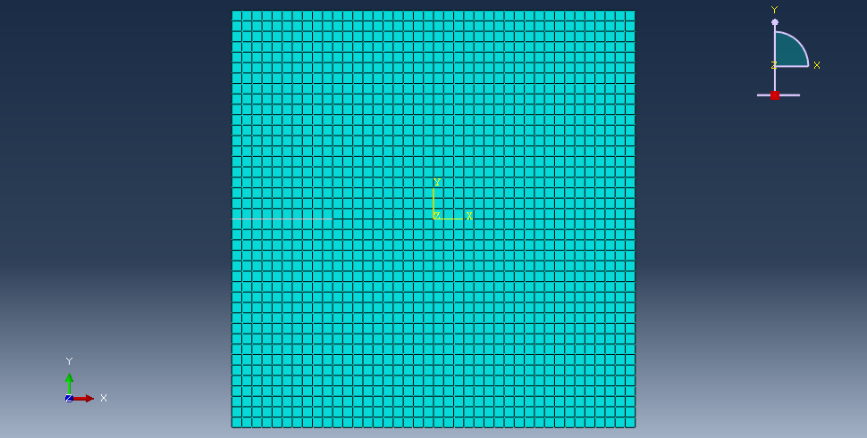
Step 6: Meshing
- Mesh Module:
- Use quad-dominated elements (e.g., CPS4R for plane stress).
- Refine mesh near the crack tip (element size ≈ 0.1 m).
- Click on Seed Part Instance and enter 0.1 for Approximate Global Size
Step 6: Analysis Step and Job Submission
- Static, General Step:
- Enable Nonlinear Geometry (for large deformations).
- Incrementation: Set initial/minimum/maximum increments (e.g., 0.01, 1e-5, 0.1).
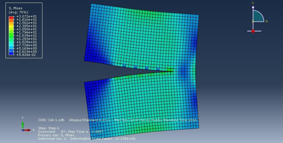
- Field Outputs: Request
STATUSXFEM,S,E,DAMAGEC,DAMAGET.
for job submission Specify the path to save the file and then click the Submit option to start solving the problem.


Sophia lander –
A very practical tutorial. The section on defining the static, general step for a quasi-static crack growth analysis was particularly helpful. The mesh refinement strategy is crucial for good results.
Dr. Rebecca Sterling –
This is an excellent guide for fracture mechanics applications. The methodology for defining the crack seam and contour integral is clearly explained. This saved my team significant time on a fatigue life project.
Dr. Amanda Fitzgerald –
This guide fills an important gap in practical fracture mechanics tutorials. The explanation of using XFEM for arbitrary crack path prediction was particularly valuable. The comparison of different crack propagation laws was very insightful.