
In this tutorial we are going to set up a finite element analysis (FEA) model in Abaqus to capture the dynamic behavior, material response, and interaction between the steel ball and aluminum sheet . Below is a detailed, step-by-step guide to perform this simulation using Abaqus/CAE, assuming a basic familiarity with the software interface.
Step 1: Define the impact Problem
- Objective: Simulate a steel ball impacting an aluminum sheet to analyze deformation, stress, strain, and potential damage.
- Parameters:
- Steel Ball: Assume a spherical ball (e.g., 10 mm diameter, density 7800 kg/m³, elastic-plastic behavior).
- Aluminum Sheet: Assume a thin square sheet (e.g., 100 mm x 100 mm x 2 mm, density 2700 kg/m³, elastic-plastic behavior).
- Impact Conditions: Initial velocity of the ball (e.g., 10 m/s downward).
- Material Properties:
- Steel: Young’s modulus = 210 GPa, Poisson’s ratio = 0.3, yield stress = 300 MPa, plastic hardening data (optional).
- Aluminum: Young’s modulus = 70 GPa, Poisson’s ratio = 0.33, yield stress = 100 MPa, plastic hardening data (optional).
- Analysis Type: Dynamic, explicit (suitable for high-speed impact).
Step 2: Create the Geometry in Abaqus
- Open Abaqus/CAE and create a new model database.
- Set Units: Abaqus is unitless, but ensure consistency (e.g., mm for length, kg for mass, s for time, N for force, MPa for stress).
- Create the Steel Ball:
- Go to the Part module.
- Create a new part: 3D, Deformable, Solid, Revolution.
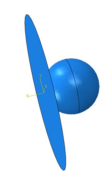
- Sketch a semi-circle (radius = 5 mm) in the XY-plane, with the center at (0,0), and revolve it 360° around the Y-axis to form a sphere.
- Name the part (e.g., “Steel_Ball”).
- Create the Aluminum Sheet:
- Create another part: 3D, Deformable, Solid, Extrusion.
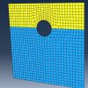
- Sketch a square (100 mm x 100 mm) in the XY-plane.
- Extrude it to a thickness of 2 mm along the Z-axis.
- Name the part (e.g., “Al_Sheet”).
- Position the Parts:
- Ensure the ball is positioned above the sheet’s center. For example, place the ball’s center at (0, 0, 7 mm) so its bottom is 5 mm above the sheet’s top surface (Z = 0 to 2 mm).
Step 3: Define Material Properties
- Go to the Property module.
- Create Materials:
- Steel:
- Name: “Steel”.
- Mechanical → Elasticity → Elastic: Young’s modulus = 210e3 MPa, Poisson’s ratio = 0.3.
- Mechanical → Plasticity → Plastic: Enter yield stress (300 MPa) and plastic strain (0). Add hardening data if available (e.g., stress vs. plastic strain curve).
- General → Density: 7.8e-9 kg/mm³ (7800 kg/m³).
- Aluminum:
- Name: “Aluminum”.
- Mechanical → Elasticity → Elastic: Young’s modulus = 70e3 MPa, Poisson’s ratio = 0.33.
- Mechanical → Plasticity → Plastic: Yield stress = 100 MPa, plastic strain = 0. Add hardening data if desired.
- General → Density: 2.7e-9 kg/mm³ (2700 kg/m³).
- Aluminum:
- Steel:
- Assign Section Properties:
- Create a Section for each part (e.g., “Steel_Section” and “Al_Section”).
- Assign the respective materials (“Steel” to the ball, “Aluminum” to the sheet).
- Assign sections to the parts: Select the entire geometry of each part in the Assign Section tool.
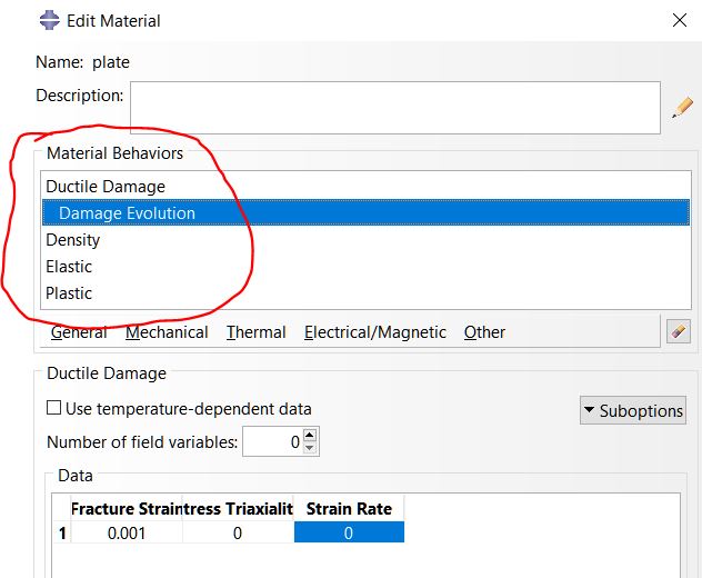 In the Ductile Damage Suboptions specify a damage evolution with a failure displacement of 0.2
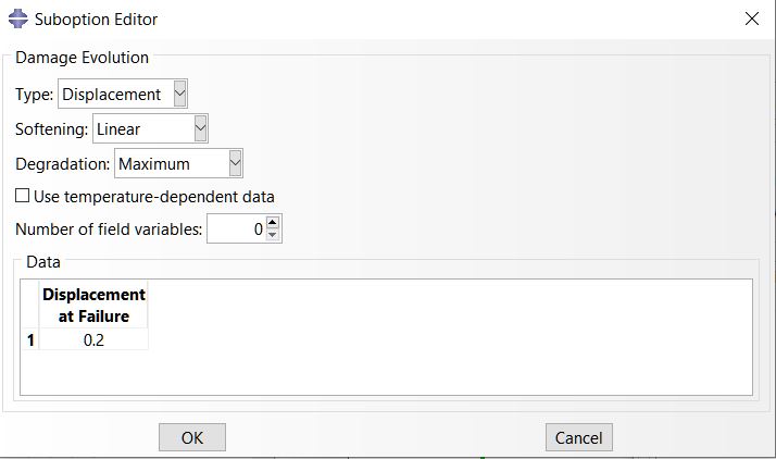 The damage evolution states that once the elements reach the failure criteria, i.e. a displacement of 0.2, then the element is deleted.
Create a section for each material and apply them to the geometry
o Ball
▪ Solid, homogenous
▪ Ball component
o Plate
▪ Shell, homogenous
▪ Shell thickness: 1
▪ Plate component
Step 4: Assemble the Parts for impact simulation
- Go to the Assembly module.
- Create Instances:
- Instance the “Steel_Ball” and “Al_Sheet” parts.
- Ensure the ball is positioned above the sheet as defined (e.g., ball center at Z = 7 mm, sheet top at Z = 2 mm).
- Verify Positioning:
- Use the Translate or Position tools to confirm the ball is centered above the sheet and offset vertically to avoid initial penetration.
Step 5: Define the Impact Analysis Step
- Go to the Step module.
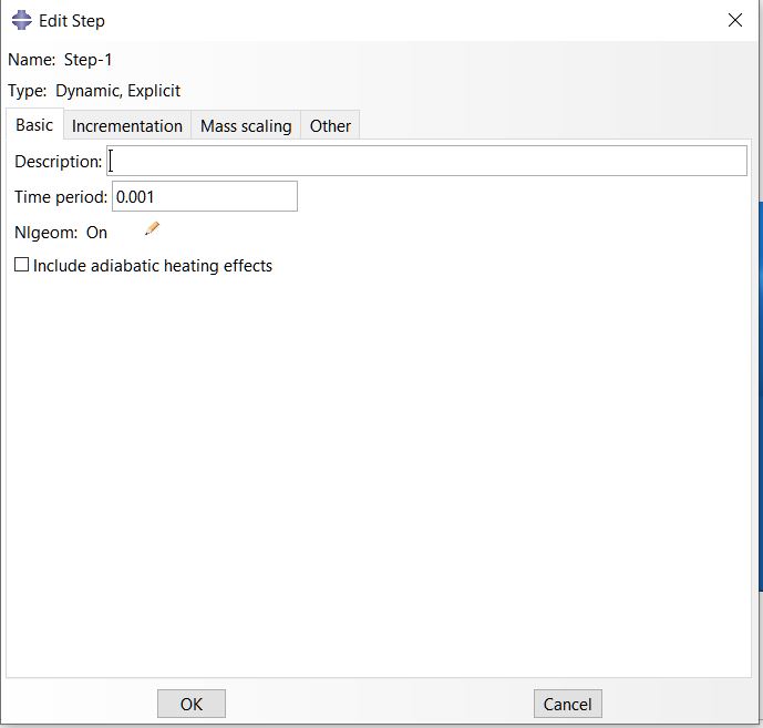
- Create a Step:
- Create a new step after the initial step: Dynamic, Explicit.
- Name: “Impact_Step”.
- Time Period: Estimate the impact duration (e.g., 0.001 s for a high-speed impact). For a 10 m/s impact over a small distance, 0.001 s is reasonable.
- Settings:
- Enable NLgeom (geometric nonlinearity) to account for large deformations.
- Set Time Incrementation to automatic for stability.
- Output Requests:
- Request field outputs: Stress (S), Strain (PE, LE), Displacement (U), Velocity (V).
- Request history outputs: Kinetic energy (ALLKE), Internal energy (ALLIE), Reaction forces (RF) at boundaries.
- Set output frequency to capture sufficient data (e.g., every 50 increments or 0.00001 s).
Step 6: Define Impact Interactions in Abaqus
- Go to the Interaction module.
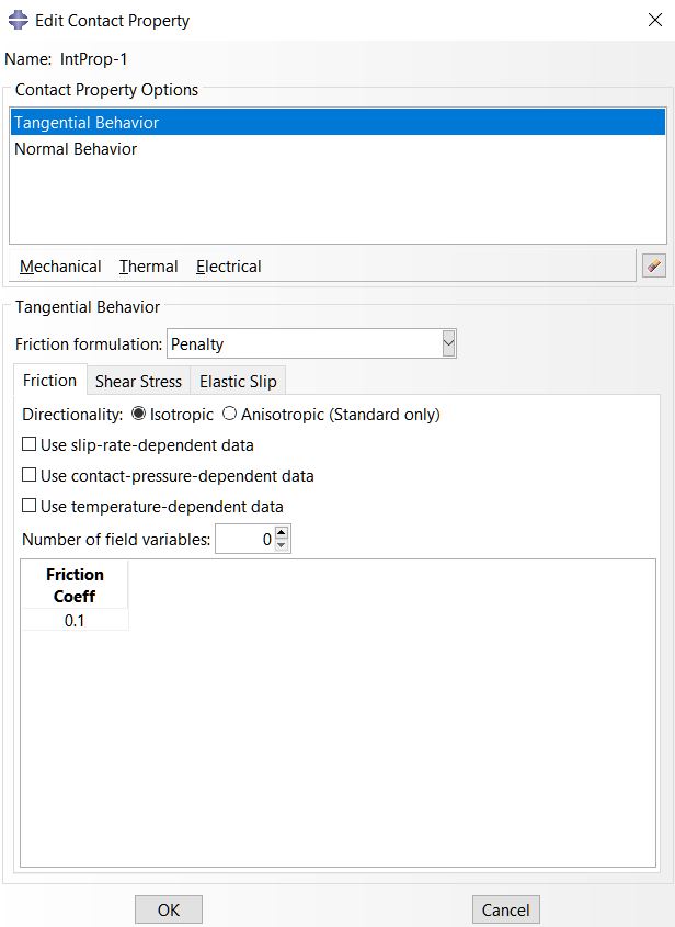
- Contact Properties:
- Create a Contact Property: Name (e.g., “Ball_Sheet_Contact”).
- Mechanical → Tangential Behavior: Friction coefficient (e.g., 0.2 for steel on aluminum).
- Mechanical → Normal Behavior: Hard contact, allow separation after contact.
- General Contact (Explicit):
- Create an Interaction: Select General Contact (Explicit).
- Assign the contact property (“Ball_Sheet_Contact”) to all surfaces.
- Include all part instances (ball and sheet) in the contact domain to account for self-contact if the sheet deforms significantly.
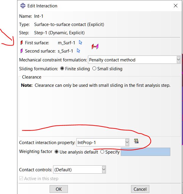
- Alternative (Surface-to-Surface Contact):
- If general contact is too computationally expensive, define a Surface-to-Surface Contact:
- Master Surface: Steel ball surface (more rigid, smaller contact area).
- Slave Surface: Top face of the aluminum sheet.
- Assign the contact property.
- Note: General contact is preferred for simplicity and robustness in explicit dynamics.
- If general contact is too computationally expensive, define a Surface-to-Surface Contact:
Step 7: Apply Boundary Conditions and Loads for impact
- Go to the Load module.
- Boundary Conditions for the Sheet:
- Create a Boundary Condition in the Initial Step.
- Name: “Fix_Edges”.
- Select the outer edges or perimeter of the sheet (e.g., all four sides).
- Apply: U1 = U2 = U3 = 0 (fix translation in X, Y, Z) to simulate clamped edges. Alternatively, fix only the bottom face or corners depending on the physical setup.
- Initial Velocity for the Ball:
- Create a Predefined Field in the Initial Step.
- Select Velocity.
- Select the entire steel ball.
- Set: V3 = -10,000 mm/s (downward, assuming Z is up). V1 = V2 = 0.
- Note: Do not apply velocity in the “Impact_Step” to avoid overriding the initial condition.
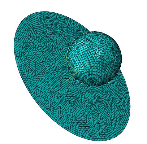
Step 8: Mesh the Model
- Go to the Mesh module.
- Seed the Parts:
- Steel Ball:
- Global seed size: ~0.5 mm (fine mesh for accuracy in contact and deformation).
- Local seed near the contact region (bottom of the ball): ~0.2 mm for higher resolution.
- Aluminum Sheet:
- Global seed size: ~2 mm.
- Local seed in the central impact zone (e.g., 20 mm x 20 mm area): ~0.5 mm to capture deformation gradients.
- Steel Ball:
- Element Type:
- Steel Ball: C3D8R (3D, 8-node linear brick, reduced integration, hourglass control) for solid elements.
- Aluminum Sheet: C3D8R for solid elements. If the sheet is very thin, consider S4R (4-node shell elements) with 5 integration points through thickness, but solid elements are better for impact.
- Mesh the Parts:
- Mesh both parts using Structured or Free meshing techniques.
- Ensure a refined mesh in the contact zone to improve accuracy.
- Verify mesh quality (no distorted elements) using the Query tool.
See more: How to Mesh a 3D Model in Abaqus: A Step-by-Step Guide
Step 9: Create and Submit the Job
- Go to the Job module.
- Create a Job:
- Name: “Ball_Impact_Simulation”.
- Select the model.
- Job Settings:
- Set Precision: Single or Double, depending on your system (Single is usually sufficient for explicit).
- Allocate sufficient memory and CPUs if available (e.g., 4 CPUs for faster computation).
- Submit the Job:
- Click Submit to run the analysis.
- Monitor the job in the Job Monitor for errors (e.g., excessive element distortion, contact issues).
- Debugging Tips:
- If the job aborts due to element distortion, refine the mesh or add Adaptive Meshing (ALE) in the Step module.
- If contact issues arise, check surface definitions or reduce the friction coefficient.
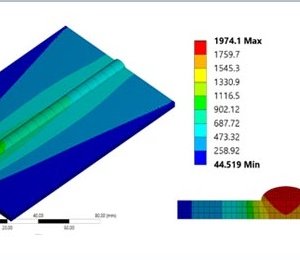
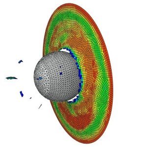
Step 10: Post-Processing and Analysis
- Go to the Visualization module.
- Open the Output Database (.odb file).
- Visualize Results:
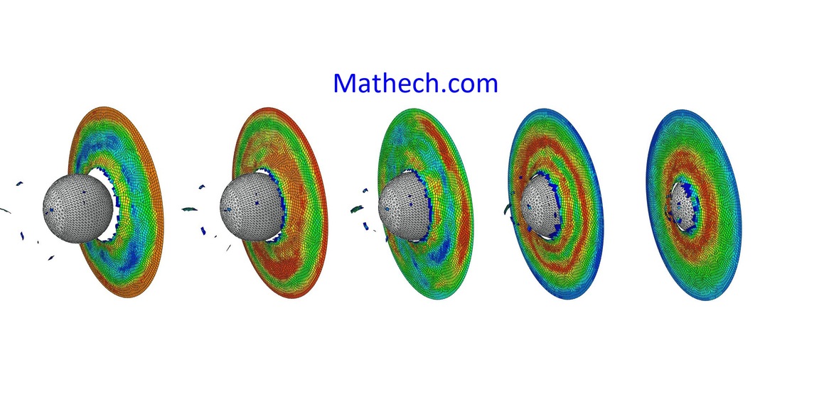
- Displacement (U): Plot the deformation of the sheet (e.g., U3 for Z-displacement) to see the dent depth.
- Stress (S): Plot von Mises stress (S, Mises) to identify high-stress regions.
- Strain (PE): Plot plastic strain (PE, PEQM) to assess permanent deformation.
- Velocity (V): Check the ball’s velocity to confirm it slows upon impact.
- Energy Outputs:
- Plot ALLKE (kinetic energy) to verify energy transfer to the sheet.
- Plot ALLIE (internal energy) to check energy absorption.
- Ensure energy balance: Total energy (ALLKE + ALLIE) should remain nearly constant.
- Create Contour Plots:
- Use Contour plots to visualize stress/strain distribution on the sheet.
- Section the sheet to view internal stresses if needed.
- Extract Quantitative Data:
- Use Probe to measure maximum displacement, stress, or strain at the impact point.
- Create XY Data plots for energy histories (e.g., kinetic vs. time).
- Validate Results:
- Compare maximum deformation or stress with analytical estimates (e.g., Hertzian contact theory for elastic impact).
- Check for unrealistic results (e.g., excessive penetration, negative energies).
Step 11: Optional Enhancements for impact simulation in Abaqus
- Damage Modeling in Abaqus:
- Add Ductile Damage for aluminum in the Material definition to simulate fracture:
- Define damage initiation (e.g., equivalent plastic strain at onset).
- Define damage evolution (e.g., softening behavior).
- Enable Element Deletion to remove failed elements.
- This allows modeling of perforation if the impact energy is high.
- Add Ductile Damage for aluminum in the Material definition to simulate fracture:
- Rigid Body Approximation:
- If the steel ball deforms minimally, model it as a Rigid Body:
- In the Part module, set the ball as Rigid instead of Deformable.
- Assign a Reference Point at the ball’s center and apply mass (e.g., 0.032 kg for a 10 mm diameter steel ball) and velocity to the reference point.
- This reduces computation time but ignores ball deformation.
- If the steel ball deforms minimally, model it as a Rigid Body:
- Adaptive Meshing:
- Enable Adaptive Meshing in the Step module for the sheet to handle large deformations without element distortion.
- Use ALE Adaptive Mesh Domain and set remeshing sweeps (e.g., 10 per increment).
- Refine Contact:
- Add Contact Stabilization in the Interaction properties to prevent initial oscillations.
- Use a small damping factor (e.g., 0.0001) to stabilize without affecting results.
- Damage Modeling in Abaqus:
Step 12: Save and Document
- Save the Model: Save the .cae and .odb files for future reference.
- Document Results:
- Export plots (e.g., stress contours, energy curves) as images or data files.
- Note key findings: Maximum deformation, peak stress, energy transfer.
- Report Assumptions:
- Document simplifications (e.g., no strain-rate effects, no damage unless modeled).
- Mention mesh size, contact settings, and boundary conditions for reproducibility.

Here are some useful links for further reading on simulating impact in Abaqus, focusing on tutorials, documentation, and practical examples:
- Simulia Abaqus Documentation
- Simulia Products
- Description: Official Abaqus documentation covering explicit dynamics, contact modeling, and impact simulations. Access through your Abaqus installation or institutional subscription (Help → Documentation).
- CAE Assistant: High-Velocity Impact Simulation
- High-Velocity Impact in Abaqus
- Description: Tutorials on high-velocity impact simulations, including projectile impacts on various materials using Abaqus/Explicit.
- HyperLyceum: Abaqus Impact Simulation Tutorials
- Impact Simulation Part 1
- Description: Part of a seven-part series with detailed tutorials on impact modeling, covering scenarios like projectile impacts and fluid-structure interactions.
- Simuleon: Abaqus Tutorials
- Abaqus Non-Linear FEA Tutorials
- Description: Includes tutorials on crash and impact simulations, such as a ball impacting an aluminum plate, with practical Abaqus/Explicit examples.
- ResearchGate: Impact Simulation Discussions
- Abaqus Impact Load Simulation
- Description: Community discussions on impact load simulations, offering practical tips and troubleshooting advice.
Contact our consulting team.

Mark Jenkins –
Could you show how to extract the impact force data over time?
James Wallace –
Excellent tutorial. It saved me a lot of time. Please do more on explicit dynamics like this.
Sarah Chen –
This was very helpful! A follow-up on modeling different material models for the ball would be great.
David Miller –
Clear and easy to follow. Is there a way to estimate the plastic deformation in the plate after impact?
Emily Rodriguez –
Thanks for this! I’d love to see a part 2 that includes thermal effects from the impact.