

This guide will show you how to build and mesh a 3D model in Abaqus. We break it down into simple, clear steps. You’ll learn the entire process from start to finish. Follow us to create reliable simulations.
1. Why a Good Mesh is the Foundation of Accurate FEA
A good mesh is the most important part of FEA. It divides your model into small pieces called elements. These elements help Abaqus calculate stresses and strains. A poor mesh will lead to incorrect answers and errors. This tutorial will ensure that you create a reliable mesh.
Step 1: Defining the Geometry – Native Creation vs. Import
Every simulation starts with geometry. First, you need to import your 3D model into Abaqus. You can create it directly in the software. Or you can import it from a CAD program. This step sets up all the subsequent steps.
1. Creating a Simple 3D Part in Abaqus/CAE
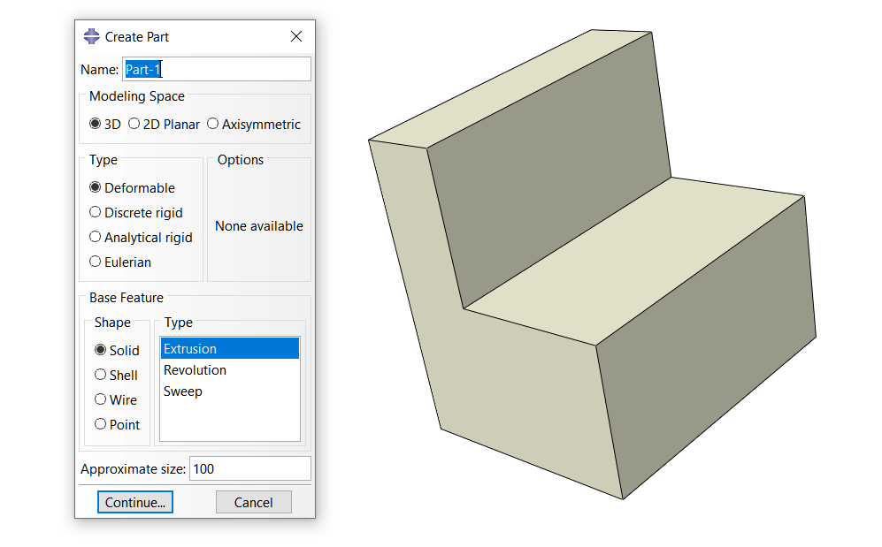
You can create simple parts within Abaqus. Use the Part module to create basic shapes. This module is great for blocks, cylinders, and plates. It’s a quick way to start a new model without any other software.
2. Importing Complex Geometry from CAD Software
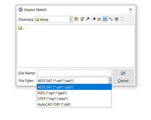
Most real-world designs are made in CAD software. You can import these models into Abaqus. Common file types are STEP and IGES. This lets you work with complex, detailed geometry from the start.
Step 2: Cut Your Model with Partitions
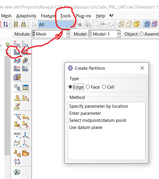
Partitioning is like cutting a complex shape into simpler pieces. This is a key step to a good mesh. These smaller, more regular shapes are easier for Abaqus to mesh correctly. This is the secret to a clean, neat mesh.
1.Why You Need to Partition
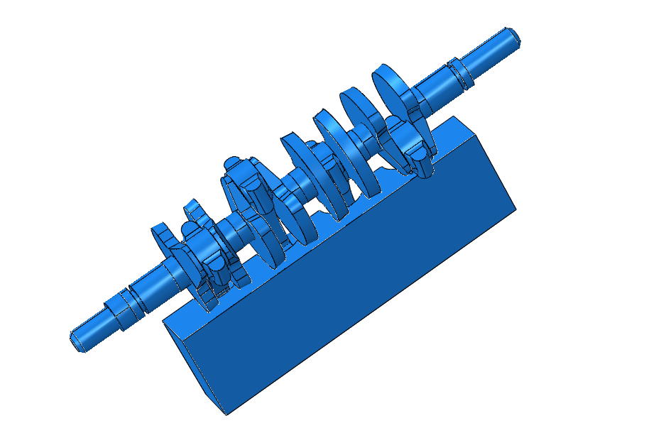
You need partitions to control your mesh. A complex shape often leads to a messy, poor-quality mesh. Partitions create straight edges and simple volumes. This allows for a structured mesh, which is more accurate and reliable.
2. How to Partition a Model
You can split your model using tools in the Part module. Use the “Define Cutting Plane” tool. You can also sketch a line to partition with. This breaks your model into smaller, more manageable sections for meshing.
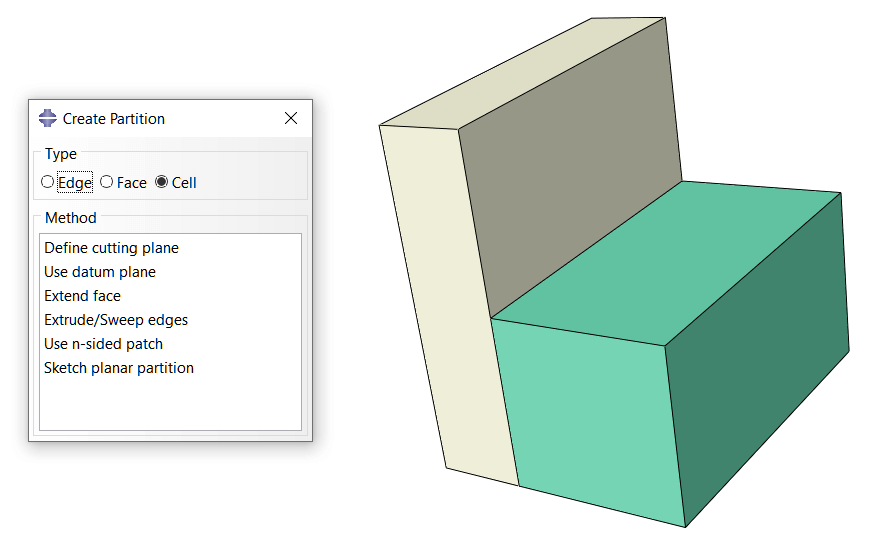
Example: Cutting a fragment
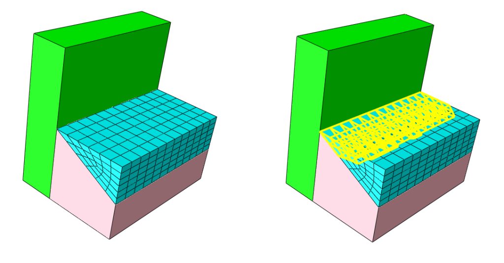
The fragment shown in the previous section has been divided into two parts. Here we can easily mesh one part of it. One of the benefits of partitioning is that we can use a finer mesh in the parts that are more sensitive, given the physics of the problem.
Check here for more examples of Abaqus projects
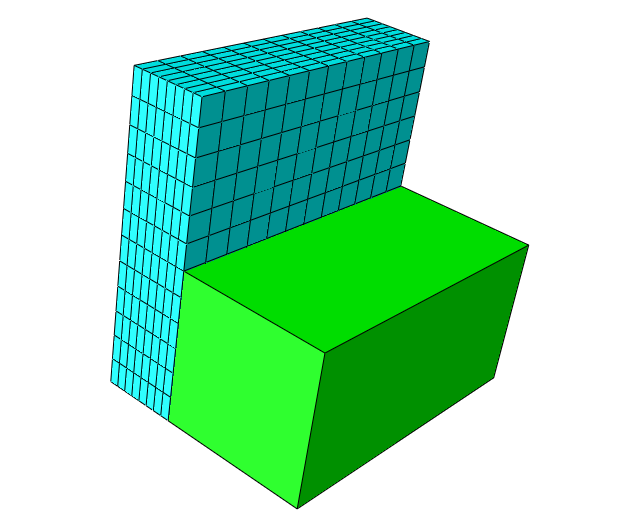
Step 3: Assigning Mesh Controls and Element Types
Now you need to tell Abaqus how to mesh. This involves choosing the appropriate element type and controls. These settings will determine the behavior and accuracy of your mesh. Getting it right here will prevent many common problems later on.
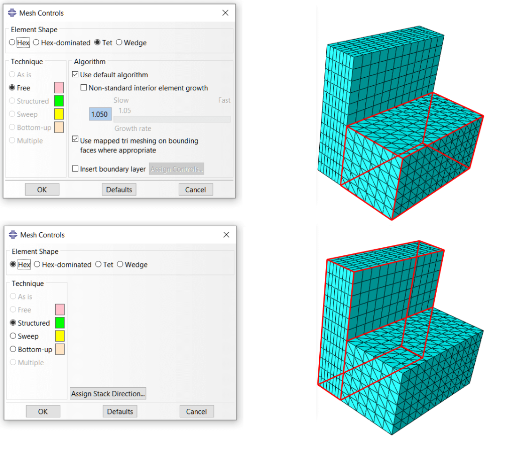
1. Choosing the Right Element Type for Your 3D Model
You must choose between hexagonal and tetrahedral elements. Hexagonal elements are often more accurate and efficient. Tetrahedral elements are better for very complex shapes. Your choice depends on the geometry of the model and your accuracy needs.
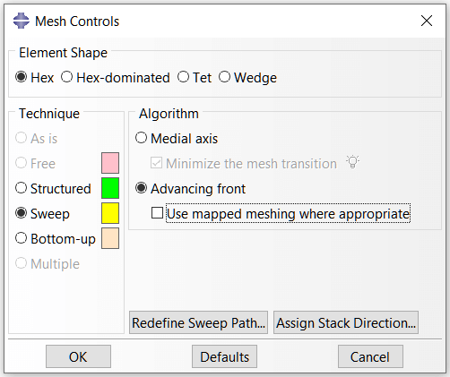
2. Configuring Mesh Controls: Structured, Swept, and Free
Mesh controls guide Abaqus in how to fill a part. You can select the “Sweep” option for a clean hexagonal mesh. The “Structured” option also provides a regular pattern. The “Free” option is used for complex areas where a 3D mesh is acceptable.
Step 4: Seeding and Generating the Mesh in Abaqus
This is where you generate the mesh. First, you set the element size using seeding. Then you tell Abaqus to generate the mesh. Finally, you need to check that it was generated without any errors.
1. Global and Local Seeding: Controlling Mesh Density
Seeding controls how fine or coarse your mesh is. A global seed sets the overall size. You can add local seeds to critical areas. A finer seed in high-stress zones gives you more accurate results there.
2. Generating the Mesh and Checking for Errors
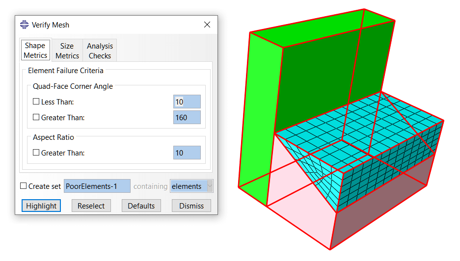
Click the “Mesh Part” button to create the mesh. Then, use the “Verify Mesh” tool. Look for any red marks that indicate failed elements. A good mesh is complete and has no error warnings.
Step 5: Verifying Mesh Quality: The Mathech Expert Checklist
Creating a mesh is not the final step. You must check its quality. Abaqus has tools to analyze the mesh. You need to look at specific metrics to ensure the mesh is good for simulation.
1. Important Quality Checks
Check the aspect ratio and Jacobian of your elements. The aspect ratio should be close to 1.0. A high Jacobian means an element is too distorted. These numbers tell you if your mesh is healthy.
Aspect Ratio
Think of the aspect ratio as a measure of an element’s shape. It compares the element’s longest side to its shortest side.
Good Aspect Ratio (Close to 1.0): The element looks like a perfect square or cube. This is ideal. It gives Abaqus a well-shaped area to calculate accurately.
Bad Aspect Ratio (Much higher than 1.0): The element is long and skinny, like a pencil or a pancake. These distorted shapes can cause inaccurate results. They make it hard for Abaqus to calculate stresses correctly.
Jacobian
The Jacobian measures how much an element is distorted when it is mapped from a perfect shape.
Good Jacobian (Close to 1.0): The element is not distorted. Its corners are well-defined.
Bad Jacobian (Much less than 1.0 or negative): The element is twisted or warped. A highly distorted or “inverted” element (negative Jacobian) will cause your analysis to fail. Abaqus cannot calculate properly with a broken element.
2. How a Bad Mesh Gives Bad Results
A bad mesh produces incorrect stress values. It can show stress concentrations that are not real. It also causes the analysis to stop with errors. A quality mesh is the only path to trustworthy results.
2. Fix Common Mesh Problems in Abaqus
Sometimes, your first mesh will have issues. Do not worry. Most mesh problems can be fixed. Here are solutions for the most frequent errors users face.
2.1. Meshing Tricky Shapes
Some organic shapes are very hard to mesh. If partitions do not work, switch to tetrahedral elements. Use a fine global seed. The “Free” mesh control often works best for these complex geometries.
2.2. Fixing a Bad Mesh
If you have twisted elements, go back a step. Try a different partitioning strategy. Use a finer local seed in the problem area. Sometimes, changing the element type is the fastest solution.
3. Conclusion
You now know how to create and mesh a 3D model in Abaqus. Start with geometry, then partition, then set controls. Always check your mesh quality. These steps will lead to successful and accurate FEA simulations in Abaqus.
4. Need Help with Mesh a Complex Model?
5. Frequently Asked Questions (FAQ) – How to Mesh a 3D Model in Abaqus
Abaqus offers several meshing techniques for 3D models, each suited for different geometry types and analysis requirements:
1. Structured Meshing:
- Uses a regular grid pattern and is available for simple geometries like bricks, cylinders, and spheres.
- Produces highly regular and high-quality elements with minimal distortion.
- Best for models that can be partitioned into simple, mappable regions.
2. Swept Meshing:
- Generates mesh by sweeping a source face mesh along a path.
- Ideal for extruded or revolved geometries (e.g., pipes, shafts, gears).
- Creates hexahedral (brick) or wedge elements with good quality.
3. Free Meshing:
- The most versatile technique, suitable for complex and irregular geometries.
- Generates tetrahedral elements by default but can also create hexahedral elements for certain regions.
- Best for organic shapes, assemblies, and models with complex internal features.
4. Bottom-up Meshing:
- Allows manual control over mesh generation by creating mesh on faces, edges, or vertices first.
- Useful for creating hybrid meshes or meshing regions with specific requirements.
- Provides maximum control but requires more user intervention.
5. Adaptive Meshing:
- Available in Abaqus/Explicit for large deformation analyses.
- Automatically refines or remeshes the mesh during the analysis to maintain element quality.
- Essential for simulations involving extreme deformation, such as metal forming or impact.
Selecting the right element type is crucial for accurate results and efficient computation. Consider these factors:
1. Element Family:
- Continuum (Solid) Elements: Used for most 3D structural analyses (e.g., C3D8, C3D10, C3D20). Suitable for general stress/strain analysis.
- Shell Elements: Ideal for thin structures where thickness is much smaller than other dimensions (e.g., S4R, S8R).
- Beam Elements: Used for slender structures like frames, columns, and shafts (e.g., B31, B32).
- Specialized Elements: Includes cohesive, gasket, spring, and mass elements for specific applications.
2. Element Order:
- Linear (First-Order) Elements: Nodes only at corners (e.g., C3D8, C3D4). Faster but can suffer from shear locking in bending-dominated problems.
- Quadratic (Second-Order) Elements: Nodes at corners and mid-edges (e.g., C3D20, C3D10). More accurate for bending, curved geometries, and high stress gradients but computationally expensive.
3. Integration Scheme:
- Full Integration: Uses all integration points. Accurate but prone to shear locking in linear elements.
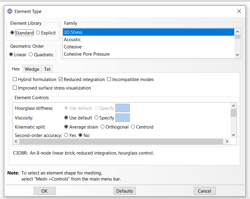
- Reduced Integration: Uses fewer integration points (e.g., C3D8R). Reduces computational cost and avoids shear locking but may cause hourglassing.
- Hybrid Elements: Designed for nearly incompressible materials (e.g., rubber, elastomers). Use these when Poisson’s ratio approaches 0.5 (e.g., C3D8H, C3D10H).
4. General Guidelines:
- Use hexahedral (brick) elements where possible for best accuracy and convergence.
- Use tetrahedral elements for complex geometries but use quadratic order to avoid over-stiffness.
- Avoid wedge (prism) elements unless necessary, as they can cause local inaccuracies.
- Perform element type validation with a simple test model before full-scale simulation.
Follow this comprehensive step-by-step guide to mesh your 3D model in Abaqus:
Step 1: Prepare the Geometry
- Import or create the 3D part in the Part module.
- Use the Partition tool to divide complex geometries into simpler, mappable regions.
- Remove unnecessary details (small fillets, holes, or chamfers) that don’t affect results but complicate meshing.
Step 2: Enter the Mesh Module
- Switch to the Mesh module from the module selector.
- Select the part or assembly instance you want to mesh.
Step 3: Set Mesh Controls
- Click on Mesh > Controls or use the toolbar icon.
- Choose the meshing technique (Structured, Swept, or Free).
- Select the element shape (Hex, Tet, Wedge, or Hybrid).
- Set algorithm options (Medial Axis or Advancing Front).
Step 4: Assign Element Type
- Click on Mesh > Element Type or use the toolbar icon.
- Select the element family (e.g., Standard, Explicit).
- Choose geometric order (Linear or Quadratic).
- Set integration scheme (Full, Reduced, Hybrid).
- Check hourglass control options for reduced integration elements.
Step 5: Define Seed Density
- Click on Seed > Part or Seed > Edge to define mesh density.
- Set approximate global size for the entire part.
- Use edge seeds to refine specific regions (e.g., stress concentration areas, contact zones).
- Apply biasing to create finer mesh near boundaries or gradients.
Step 6: Generate the Mesh
- Click on Mesh > Part or Mesh > Region to generate the mesh.
- Alternatively, use the mesh icon from the toolbar.
- Monitor the status bar for any errors or warnings during generation.
Step 7: Verify Mesh Quality
- Go to Mesh > Verify to check element quality.
- Inspect aspect ratio, element angles, and Jacobian determinants.
- Use color mapping to visualize element quality metrics.
- Refine or modify the mesh if quality criteria are not met.
Step 8: Assign Sections and Materials
- Return to the Property module to assign material properties and section definitions.
- Ensure the mesh is compatible with the assigned section type.
Step 9: Assemble and Run
- Switch to the Assembly module and instance the part.
- Set up the analysis step, loads, and boundary conditions.
- Submit the job and monitor convergence.
Improving mesh quality is essential for accurate results and successful convergence. Here are proven strategies:
1. Partition Complex Geometries:
- Use the Partition tool to divide the geometry into simpler, mappable regions.
- Create partitions at geometric features, material interfaces, and regions of interest.
- For swept meshing, ensure the swept region has a consistent cross-section.
2. Optimize Element Size:
- Use global seed size that balances accuracy and computational cost.
- Refine mesh in critical regions (stress concentrations, contact, high gradients).
- Use biasing to transition from fine to coarse mesh gradually.
- Perform a mesh convergence study to determine optimal element size.
3. Avoid Common Errors:
- Negative Jacobian: Occurs when elements are severely distorted. Use quadratic elements or refine the mesh.
- High Aspect Ratio: Keep aspect ratio below 10:1 for most analyses. Use biasing or partitioning to improve.
- Warped Elements: Avoid creating elements with non-planar faces. Use structured meshing for better control.
- Shear Locking: Use reduced integration or higher-order elements for bending-dominated problems.
- Hourglassing: Enable hourglass control in reduced integration elements (enhanced or stiffness control).
4. Use Mesh Verification Tools:
- Run Mesh > Verify to check element quality metrics.
- Check Jacobian values (should be positive).
- Inspect element distortion using color mapping.
- Review the .dat file for mesh warnings and errors.
5. Advanced Techniques:
- Use adaptive meshing in Abaqus/Explicit for large deformations.
- Consider hybrid meshing (combining hex and tet elements) for complex geometries.
- Use mesh seeds with curvature control to capture curved geometry accurately.
- Apply mesh constraints to ensure compatible meshes at interfaces.
6. Practical Tips:
- Always test the mesh with a simple linear elastic analysis before running full nonlinear simulations.
- Use symmetry whenever possible to reduce model size and simplify meshing.
- Document mesh settings for reproducibility and troubleshooting.
Meshing assemblies and complex geometries requires careful planning and specialized techniques. Follow these best practices:
1. Assembly Meshing Strategy:
- Mesh each part separately if they are independent components.
- Use compatible meshes at interfaces when using tie constraints or contact.
- Consider mesh independent meshing for parts that interact through contact.
- Use assembly-level seeds to control mesh density across multiple parts.
2. Contact Interface Meshing:
- Ensure sufficient element density in contact zones to capture pressure distribution.
- Use similar element sizes on master and slave surfaces for better contact detection.
- Refine mesh near contact edges and corners where stress concentrations occur.
- Avoid using coarse mesh on surfaces with high curvature in contact.
3. Handling Complex Geometries:
- Use partitioning extensively to break down complex shapes into mappable regions.
- Consider virtual topology to simplify geometry by merging small faces or edges.
- Use tetrahedral elements for highly organic or irregular shapes.
- Apply local mesh refinement using partition-based seeding.
4. Mesh Transition and Grading:
- Use mesh biasing to create smooth transitions between fine and coarse regions.
- Avoid abrupt changes in element size that cause stress artifacts.
- Use wedge elements (prisms) as transition elements between hex and tet meshes.
5. Performance Optimization:
- Use reduced integration elements (C3D8R) for large models to reduce computational cost.
- Apply symmetry boundary conditions to model only a fraction of the assembly.
- Use submodeling to refine only critical regions of large assemblies.
- Consider parallel meshing in Abaqus/CAE for very large models.
6. Quality Assurance:
- Perform mesh verification on each part before assembly.
- Check node equivalence at interfaces if using tied contacts.
- Run a check job (Data Check) to identify meshing issues before full analysis.
- Review element quality metrics globally and locally in critical regions.
7. Common Pitfalls to Avoid:
- Overly fine mesh everywhere—refine only where needed.
- Incompatible meshes at interfaces—use matching seeds or tie constraints.
- Ignoring warnings from the mesh verification tool.
- Meshing too quickly without planning the strategy for complex assemblies.






This made meshing my turbine blade model much easier. The tip about virtual topology for small features was a game-changer. Thank you!
We use this as training material for new hires. The mesh quality metrics section is particularly useful. A part 2 on troubleshooting poor-quality elements would be valuable
Perfect for my graduate research! The explanation of element types was great. Is there a rule of thumb for when to use tetrahedral vs. hexahedral elements for accuracy?
This guide saved me so much time. The section on partitioning to control the mesh was exactly what I needed for a complex injection mold. Any tips for hex-dominant meshing on organic shapes?
Very clear steps! I used this for a bracket analysis. Could you do a follow-up on setting local mesh seeds and mesh convergence studies?
Finally, a guide that explains mesh controls clearly. The visuals on swept meshing helped a lot. How do you decide between medial axis and advancing front for a sweep?