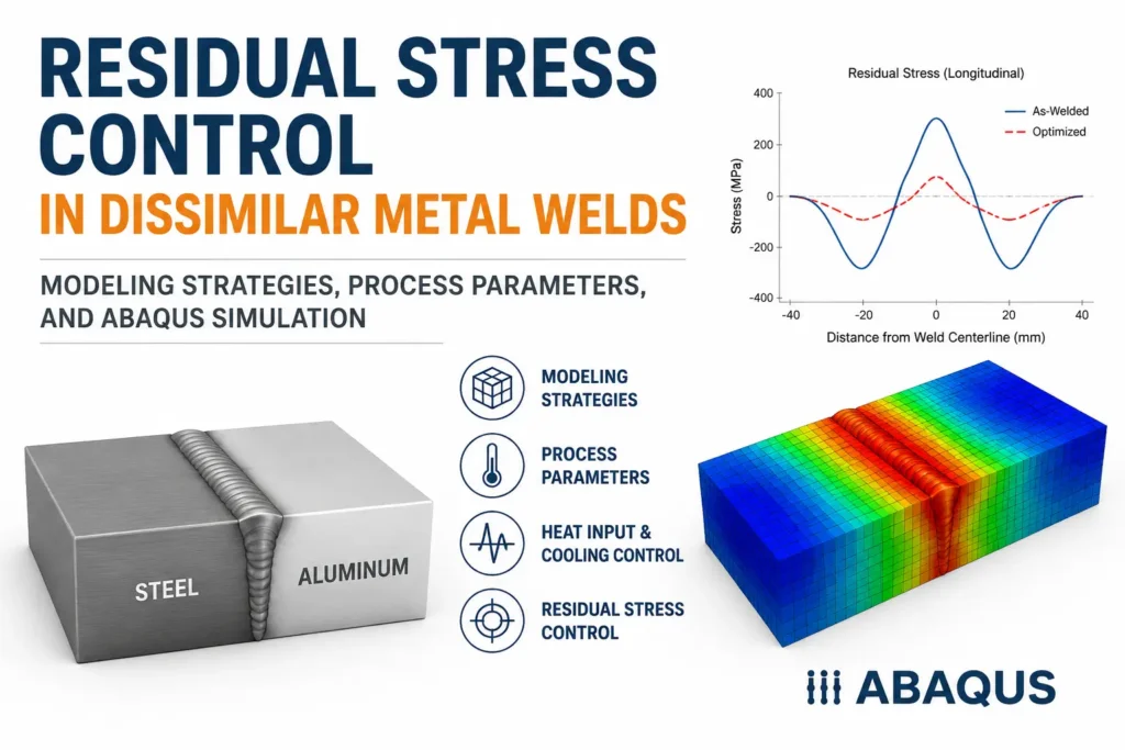
Controlling residual stress in dissimilar metal welds requires careful control of the thermal cycle, material mismatch, welding sequence, and mechanical restraint. Differences in thermal expansion, conductivity, strength, and high-temperature behavior can create significant stress concentrations around the fusion zone and material interface.
In engineering practice, finite element welding simulation provides a practical way to evaluate these effects before changing the welding procedure. This article focuses on an Abaqus-based workflow for predicting and controlling residual stress, including heat-source calibration, temperature-dependent material properties, realistic boundary conditions, weld-pass sequencing, mesh refinement, and validation.
Practical Strategy for Residual Stress Control in Dissimilar Metal Welds
Residual stress control in dissimilar metal welds requires more than reducing the overall heat input. The thermal and mechanical mismatch between the two materials can strongly influence stress localization, plastic strain, distortion, and the final residual stress field.
A reliable engineering workflow should therefore combine thermal analysis, accurate material data, realistic heat-source modeling, and mechanical simulation.
Predict the transient temperature field and thermal cycles during welding.
Define thermal expansion, conductivity, strength, and other properties as functions of temperature.
Represent the actual welding process using an appropriate moving heat-source model.
Transfer the calculated temperature history into the mechanical analysis.
Capture high-temperature yielding and plastic strain during heating and cooling.
Reproduce actual fixture conditions and avoid artificial mechanical constraints.
Evaluate longitudinal, transverse, and through-thickness residual stresses.
Compare thermal, distortion, and residual-stress predictions with reliable reference data.
Recommended Abaqus Modeling Strategy
For residual stress analysis in Abaqus, the most robust approach is usually a transient heat-transfer analysis followed by a mechanical analysis. The temperature history calculated by the thermal model becomes the thermal load for the mechanical model.
This sequential approach allows the analyst to evaluate how thermal expansion mismatch, material strength differences, plastic deformation, and mechanical restraint interact throughout the welding cycle and influence the final residual stress field.
Need Help With Your Welding Simulation Project?
Get expert support for Abaqus modeling, FEA, thermal analysis, welding simulation, material modeling, and complex engineering problems.
Tell us about your project, requirements, simulation type, and timeline.
Practical Examples for Dissimilar Material Welding
| Industry / Area | Materials joined | Challenge | Technique | Outcome |
|---|---|---|---|---|
| 🚢 Marine | Al AA6082 + SS AISI316 | Brittle intermetallics, corrosion | Friction Stir Welding (FSW) | ✔ viable strong joint, limited brittle phases |
| 🌉 Bridges | CR A709 50CR + CS A36/50W | Galvanic/pitting corrosion; inspection unreliable | Conventional arc welding | ⚠️ not recommended long‑term durability fails |
| 🚄 High‑speed rail | Mn Austenitic Mn + CS Carbon steel | Cracking due to incompatible metallurgy | Buttering (16Mn‑16Cr / 25Cr‑20Ni layer) | ✔ proven strength near parent metal |
| 🛰️ Space / UHV | BeCu Beryllium‑Copper + SS SUS | Unweldable with conventional methods | Blue + IR hybrid laser | ✦ breakthrough exceeds SS tensile strength |
| ✈️ Aerospace AM | Al Aluminium + SS Stainless steel | Metallurgical incompatibility | Radial deposition (WAAM, mechanical interlock) | ✦ emerging lightweight bimetallic couplers |
| 🛢️ Oil & Gas / LNG | SS Stainless + Al Aluminium (clad) | High‑pressure corrosive fluids | Explosion welding | ✔ industrial leak‑proof durable components |
| 📌 Key takeaway: Dissimilar welding is powerful but requires careful process selection — not every combination works. | ||||
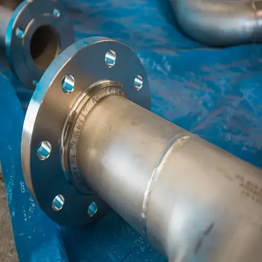
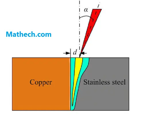
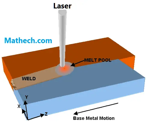
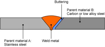
Why Dissimilar Metal Welds Require Different Residual Stress Control
The most important factor in residual stress control in dissimilar metal welds is the mismatch between the two materials. Consider a joint between austenitic stainless steel and carbon steel. Their thermal expansion coefficients, thermal conductivities, yield strengths, elastic moduli, and temperature-dependent behavior can differ significantly.
During Heating
- The two materials expand at different rates.
- The weld region becomes locally softened.
- Plastic deformation can develop near the fusion zone.
- Stronger or less conductive material can constrain deformation.
During Cooling
- The weld metal contracts as its temperature decreases.
- The surrounding base metals restrict this contraction.
- Tensile residual stresses can develop around the weld.
- Stress concentrations can occur near the fusion boundary and HAZ.
The final stress state therefore depends on the complete welding thermal cycle, rather than on the peak temperature or heat input alone.
Engineering interpretation: Residual stress is governed by the interaction between thermal expansion mismatch, material strength mismatch, geometric constraint, and weld thermal history.
Therefore, reducing a single parameter does not necessarily minimize the final residual stress. For example, reducing heat input may change the thermal gradient without eliminating the stresses generated by material mismatch or mechanical restraint.
Establish the Dissimilar Material Pair Before Modeling
Before constructing the Abaqus model, identify the dominant material mismatch.
A useful comparison table is:
| Property | Material A | Material B | Modeling Importance |
|---|---|---|---|
| Elastic modulus | High | ||
| Yield stress | Very high | ||
| Thermal conductivity | High | ||
| Specific heat | High | ||
| Thermal expansion | Very high | ||
| Density | Medium | ||
| Poisson’s ratio | Medium | ||
| Plastic behavior | Very high | ||
| Solidus temperature | High | ||
| Liquidus temperature | High |
Temperature-dependent properties are particularly important close to the fusion zone.
Using room-temperature properties throughout the analysis can produce a visually reasonable temperature field while generating an unreliable residual stress prediction.
Abaqus Workflow for Residual Stress Control in Dissimilar Metal Welds
A reliable Abaqus workflow for residual stress control should be built progressively. Start with the welding geometry and material data, then introduce thermal expansion and temperature-dependent behavior before evaluating the final stress field.
Step 1: Build the Welding Geometry
The model should reproduce the geometric features that significantly affect thermal and mechanical behavior. Depending on the application, consider including:
- Two dissimilar base metals
- Weld metal
- Fusion zone
- Heat-affected zones when appropriate
- Joint preparation
- Plate or pipe thickness
- Clamps or fixtures
- Symmetry planes
- Relevant weld passes
Do not automatically model every geometric detail. For residual stress prediction, prioritize the joint configuration, thickness, weld size, fusion-zone geometry, weld-pass sequence, and mechanical constraint.
A highly detailed geometry cannot compensate for an incorrect thermal model, material definition, or boundary condition.
Step 2: Define Separate Material Models
Each base metal should have its own material definition. This is essential for capturing the material mismatch that drives residual stress in dissimilar joints.
Thermal Analysis
- Density
- Thermal conductivity
- Specific heat
Mechanical Analysis
- Elastic modulus
- Poisson’s ratio
- Thermal expansion coefficient
- Yield stress
- Plastic stress-strain response
Where reliable experimental data are available, define the relevant properties as functions of temperature. This becomes particularly important near the fusion zone and HAZ.
Temperature-Dependent Elastic Properties
Abaqus can represent the elastic modulus and Poisson’s ratio as temperature-dependent properties:
This is particularly important at elevated temperatures because the elastic modulus can decrease significantly during welding.
Temperature-Dependent Yield Stress
For plasticity, the yield behavior should account for both plastic strain and temperature:
The reduction in yield stress at high temperature strongly affects the amount of plastic strain generated during welding. Neglecting this effect can distort the predicted residual stress field.
Step 3: Define Thermal Expansion Correctly
Thermal expansion mismatch is one of the main drivers of residual stress in dissimilar joints. The thermal strain can be approximated by:
where T0 is the reference temperature, T is the current temperature, and α(T) is the temperature-dependent coefficient of thermal expansion.
For two dissimilar materials, the thermal expansion mismatch can be expressed as:
This mismatch becomes particularly important when the two materials are strongly constrained during heating and cooling.
Common modeling error: assigning the same thermal expansion coefficient to both materials simply because the mechanical model converges more easily. This can significantly distort the predicted residual stress field in a dissimilar metal weld.
Engineering Priority
Build the model around the actual material mismatch and thermal history. Improving geometric detail is useful only after the heat source, temperature-dependent material properties, thermal expansion, and mechanical constraints are physically justified.
Heat-Source Modeling for Residual Stress Prediction
Use a Transient Moving Heat Source
A moving heat source is generally preferable to a simplified uniform heat input.
For arc welding, commonly used approaches include:
- Goldak double-ellipsoidal heat source
- Gaussian surface heat source
- Volumetric Gaussian heat source
- Conical heat source
For laser welding:
- Gaussian surface heat source
- Volumetric Gaussian source
- Conical volumetric source
- Keyhole-inspired volumetric models
The heat-source selection should reflect the actual welding process.e.
Mechanical Boundary Conditions and Their Effect on Residual Stress
Boundary conditions can change the predicted residual stress substantially.
This is particularly important for dissimilar joints because the materials already impose strong mutual constraints.
Avoid Artificially Rigid Constraints
A common modeling mistake is fixing too many degrees of freedom.
For example, fixing an entire plate edge can prevent the natural thermal contraction that occurs after welding.
The result may be:
- Excessive tensile residual stress
- Unrealistic distortion
- Localized stress peaks
- Artificial plastic deformation
Instead, reproduce the actual fixture condition as closely as possible.
Model Welding Fixtures When Necessary
If the real welding procedure uses clamps, fixtures, backing plates, or strong restraints, their influence may need to be included.
There are two practical approaches.
Simplified Constraint Model
Represent the fixture using appropriate boundary conditions.
This is efficient when the fixture stiffness is much higher than the welded structure.
Explicit Fixture Model
Model the fixture using:
- Rigid bodies
- Analytical rigid surfaces
- Elastic components
- Contact interactions
This is more computationally expensive but can provide better predictions when fixture compliance affects distortion or residual stress.
Sequential Thermal-Mechanical Analysis in Abaqus
A robust workflow is:
Thermal model → Temperature history → Mechanical model → Residual stress
The thermal analysis calculates:
The mechanical model then uses this field as a thermal load.
The mechanical problem becomes:
This allows the simulation to capture:
- Thermal expansion
- Thermal contraction
- Plastic deformation
- Material softening
- Constraint effects
- Residual stress
Choosing Abaqus Element Types
For a 3D transient thermal model, suitable elements can include:
- DC3D8
- DC3D20
- Other appropriate heat-transfer elements
For the mechanical analysis:
- C3D8
- C3D8R
- C3D20
- Other appropriate continuum elements
The thermal and mechanical meshes should be sufficiently compatible if the temperature field is transferred directly between analyses.
Near the weld, mesh refinement is normally required.
Mesh Refinement Near the Fusion Zone
Residual stresses can vary rapidly near:
- Fusion boundaries
- Weld toes
- Weld roots
- Heat-affected zones
- Material interfaces
A coarse mesh can smooth these gradients and underestimate local stress concentrations.
A practical strategy is to use:
- Fine mesh near the weld
- Intermediate mesh in the HAZ
- Coarser mesh farther from the weld
Perform at least one mesh-sensitivity study.
For example:
| Mesh | Weld-region size | Peak longitudinal stress | Distortion |
|---|---|---|---|
| Coarse | 2.0 mm | — | — |
| Medium | 1.0 mm | — | — |
| Fine | 0.5 mm | — | — |
The goal is not necessarily to obtain identical peak stresses.
Instead, determine whether engineering quantities of interest have converged.
Residual Stress Components to Evaluate
Do not evaluate residual stress using von Mises stress alone.
For welded structures, extract the individual stress components.
The most useful quantities often include:
Longitudinal Stress
This is usually important along the weld direction.
Transverse Stress
This can be significant near the weld and joint boundaries.
Through-Thickness Stress
This becomes particularly important in thick sections and highly constrained joints.
Equivalent Stress
Von Mises stress remains useful for evaluating yielding and plastic deformation, but it should not replace directional residual-stress analysis.
Residual Stress Control Through Welding Parameters
The most practical methods for controlling welding residual stress are usually related to the welding process itself. Heat input, welding speed, pass sequence, interpass temperature, post-weld heat treatment, and buttering can all influence the final stress state.
In Abaqus, these parameters can be incorporated into a sequential thermo-mechanical analysis. This allows the thermal history and resulting mechanical response to be evaluated together.
Reduce Excessive Heat Input
Increasing heat input generally increases the heated volume and thermal expansion of the welded region. This can increase thermal gradients and plastic deformation, which influence the final residual stress field.
However, simply minimizing heat input is not always the correct strategy. Excessively low heat input can compromise weld quality and produce incomplete fusion or insufficient penetration.
Control Welding Speed
Welding speed directly affects the amount of energy deposited per unit length for a moving heat source. For a constant effective power, the line energy can be expressed as:
where Q is the effective power and v is the welding speed.
Lower welding speed increases the energy deposited per unit length. Higher welding speed generally reduces the thermal footprint. However, the resulting residual stress depends on joint geometry, material properties, heat source characteristics, and restraint conditions.
Optimize Weld Pass Sequence
For multipass welding, the pass sequence can strongly influence the final residual stress distribution. Each new pass changes the temperature field and mechanical state created by the previous passes.
Instead of evaluating only one welding sequence, compare several practical alternatives during the simulation.
Deposit all passes in the same progressive direction.
Distribute welding passes to improve thermal and mechanical balance.
Alternate deposition between opposite sides of the joint.
Reverse local deposition direction to modify heat accumulation.
Use a geometrically balanced sequence where applicable.
The optimum sequence depends on joint geometry, material properties, welding conditions, and structural restraint. Therefore, pass sequence should be treated as a simulation variable rather than a universal rule.
Control Interpass Temperature
For multipass welding, interpass temperature should be treated as an important process parameter. The temperature remaining in the joint before the next pass affects the subsequent thermal cycle.
A high interpass temperature can increase the accumulated thermal field. A low interpass temperature can increase thermal cycling between passes. Both conditions can alter the mechanical response of the welded structure.
Post-Weld Heat Treatment
Post-weld heat treatment (PWHT) can significantly change the residual stress state by heating the welded component and allowing stress redistribution and relaxation.
In Abaqus, PWHT can be represented by an additional thermal step after the welding sequence. A simplified simulation sequence is:
- Complete the welding simulation.
- Allow controlled cooling after welding.
- Heat the component to the PWHT temperature.
- Hold the component at the specified temperature.
- Cool the component under controlled conditions to ambient temperature.
The mechanical response during PWHT depends strongly on the temperature dependence of the material model.
For high-temperature applications, creep and stress relaxation may become important. Neglecting these mechanisms can make a PWHT residual-stress prediction unrealistic.
Interlayer and Buttering Strategies
Buttering can be particularly useful for controlling residual stress in severe dissimilar-metal joints. A buttering layer creates a transition between the two base metals and modifies the local thermal and mechanical response.
The engineering objectives of buttering can include:
- Reducing abrupt material-property mismatch
- Improving metallurgical compatibility
- Controlling dilution
- Modifying thermal expansion mismatch
- Reducing local stress concentration
If the buttering layer has significant dimensions, model it as a separate material region with its own thermal and mechanical properties. Do not simply assign the buttering properties to one of the base metals.
Summary of Welding Parameters for Residual Stress Control
In practice, residual stress control rarely depends on one parameter. A better approach is to evaluate several welding conditions and compare the resulting temperature history, plastic strain, distortion, and residual stress distribution.
Abaqus makes this comparison possible by combining a transient thermal analysis with a subsequent mechanical analysis. This provides a quantitative way to evaluate how welding parameters influence the final structural state.
Modeling Weld Metal and Material Deposition
For multi-pass welding, the weld material does not exist mechanically before deposition.
Abaqus can represent this using element activation strategies such as:
- Model Change
- Element activation/deactivation approaches
- Progressive deposition techniques
A typical workflow is:
- Initially deactivate weld elements.
- Activate elements for the first pass.
- Apply the welding heat source.
- Allow cooling.
- Activate the next pass.
- Repeat the process.
- Continue until all passes are deposited.
- Cool the complete structure to ambient temperature.
- Evaluate residual stress.
This approach is substantially more realistic than treating the complete weld as present from the beginning.
Dissimilar Interface Modeling
The material interface deserves special attention.
At minimum, ensure that:
- Thermal continuity is properly represented.
- Mechanical compatibility is appropriate.
- Mesh quality is acceptable.
- Material properties change at the correct location.
For welded joints with metallurgical transition zones, a sharp interface may not represent the real structure.
A more advanced model can introduce:
- Transition materials
- Composition-dependent properties
- Graded material zones
- Explicit HAZ regions
However, additional complexity should only be introduced when experimental evidence supports it.
Using DFLUX for a Moving Welding Heat Source
For a moving welding source, the heat flux location can be calculated from the current analysis time.
For example:
where (z_c) is the heat-source center.
A Gaussian source can then be written conceptually as:
In Abaqus, a DFLUX subroutine can calculate the instantaneous heat flux at each integration location.
For a welding simulation, verify that:
- The heat source moves at the correct speed.
- The power is correctly normalized.
- The source remains inside the weld path.
- The heat source switches correctly between passes.
- The time-dependent position is consistent with the step time.
A frequent implementation error is mixing global analysis time with step time.
For multi-step simulations, carefully distinguish:
TIME(1)— current step timeTIME(2)— total analysis time
The choice affects the calculated heat-source position.
Thermal Boundary Conditions
The thermal model should include realistic heat losses.
Depending on the application:
- Convection
- Radiation
- Conduction to fixtures
- Contact heat transfer
may be required.
Radiation becomes increasingly important at elevated temperatures.
The radiative heat flux can be represented as:
where:
- () is emissivity
- () is the Stefan-Boltzmann constant
- () is surface temperature
- () is ambient temperature
Using a constant convection coefficient and neglecting radiation can be acceptable for preliminary studies, but it should be justified for high-temperature welding simulations.
Validation of Residual Stress Predictions
Residual stress validation is more difficult than thermal validation.
Potential experimental techniques include:
- X-ray diffraction
- Neutron diffraction
- Hole-drilling methods
- Contour method
- Ultrasonic techniques
The experimental measurement depth and spatial resolution must be considered when comparing results.
For example, comparing a surface X-ray measurement directly with a through-thickness finite-element value can be misleading.
Extract the numerical result at a location and depth comparable to the experimental measurement.
Common Causes of Unrealistic Residual Stress Results
Unrealistic residual stress results in welding simulation often come from modeling assumptions rather than limitations of the finite element method. The following issues should be checked before using Abaqus results for engineering decisions.
Using Constant Material Properties
Constant material properties can produce unrealistic thermal expansion and plastic deformation, particularly at high welding temperatures.
Incorrect Reference Temperature
Thermal strain depends directly on the reference temperature used in the model.
If Tref is incorrectly defined, the entire residual stress field can shift. It should represent the physical stress-free state assumed by the model.
Excessive Mechanical Constraints
Over-constraining the structure is one of the fastest ways to generate unrealistic residual stresses. Check whether every fixed degree of freedom corresponds to a real physical restraint.
Poor Heat-Source Calibration
A heat source can produce the correct total energy while still generating an incorrect residual stress field if its spatial distribution is wrong.
Ignoring Weld Pass Sequence
For multipass welding, changing the deposition sequence changes the thermal and mechanical history. The final residual stress field can therefore change significantly.
Ignoring Material Mismatch
Assigning averaged properties to both materials defeats one of the main purposes of a dissimilar welding model.
Evaluating Only von Mises Stress
A single equivalent-stress contour cannot describe the complete residual stress state.
Insufficient Mesh Resolution
A coarse mesh near the weld can smear thermal and stress gradients, particularly around the fusion zone and material interface.
Engineering check: Before interpreting an Abaqus residual stress contour, verify the material data, reference temperature, heat-source calibration, mechanical constraints, weld sequence, and mesh sensitivity. A detailed contour is not evidence of an accurate prediction unless these fundamentals are physically justified.
A Recommended Abaqus Simulation Sequence
A practical Abaqus workflow for residual stress prediction should separate material preparation, thermal calibration, mechanical analysis, and validation. This staged approach makes it easier to identify errors and isolate the effect of individual welding parameters.
The following sequence provides a reliable framework for developing and calibrating a thermo-mechanical welding simulation.
Simulation Workflow Overview
Stage 1: Material Data Preparation
Begin by collecting temperature-dependent material properties for both the thermal and mechanical analyses. Accurate material data becomes increasingly important when the weld region experiences large temperature changes.
Stage 2: Build the Thermal Model
Build the geometry and define the thermal properties required for the transient heat-transfer analysis. Include appropriate convection and radiation conditions when they are relevant to the welding process.
Select an appropriate heat-transfer element type and use a mesh that can adequately resolve the weld region and expected thermal gradients.
Stage 3: Implement the Heat Source
Implement the moving heat source using an appropriate Abaqus load definition or a user subroutine such as DFLUX. The heat-source model should reproduce the spatial and temporal behavior of the actual welding process.
Stage 4: Calibrate the Thermal Model
Do not proceed directly to residual stress prediction without validating the thermal model. First compare the simulated thermal behavior with experimental or reliable reference data.
Compare predicted width, depth, and penetration.
Check temperatures at representative locations.
Compare heating and cooling histories.
Stage 5: Build the Mechanical Model
After calibrating the thermal model, transfer the calculated temperature history to the mechanical analysis. The temperature field acts as a thermal load that produces thermal expansion and contraction.
The mechanical model should include temperature-dependent mechanical properties and thermal expansion data whenever the temperature range makes these effects significant.
Stage 6: Calibrate Constraints and Boundary Conditions
Fixture and boundary conditions strongly influence residual stress and distortion. Over-constraining the model can produce unrealistic stresses, while under-constraining it can produce unrealistic rigid-body motion.
Stage 7: Calculate the Residual Stress
Continue the simulation through the complete welding sequence and subsequent cooling period. The structure should reach the required reference or ambient condition before final residual stresses are extracted.
Residual stress should be evaluated after the relevant thermal and mechanical transients have sufficiently decayed. If the component is unclamped after welding, include the corresponding release of restraints when it is important to the physical problem.
Stage 8: Extract Stress and Distortion Results
Extract the stress and deformation quantities required for engineering evaluation. Use paths, sections, and field outputs that correspond to experimental measurement locations whenever possible.
Stage 9: Perform a Welding Parameter Study
After the baseline model has been validated, vary selected welding parameters and compare the resulting residual stress fields. This step converts the simulation from a single prediction into a process-design tool.
Recommended Strategy for Reliable Results
The most reliable approach is to validate the simulation progressively. First verify the material data and units. Then calibrate the thermal model and heat source. Next, validate the mechanical response and restraint conditions. Only after these steps should you use the model for residual stress optimization.
This staged workflow reduces the risk of attributing a numerical error to a welding parameter. It also makes parameter studies more meaningful because the baseline model has already been calibrated.
Advanced Considerations for Dissimilar Metal Welding
Dissimilar metal welding introduces additional challenges that are not always captured by a conventional thermo-mechanical welding model. Differences in thermal expansion, mechanical properties, phase behavior, and metallurgical response can strongly affect the predicted residual stress field.
For advanced dissimilar metal welding simulations in Abaqus, the model may need to include transformation-induced strain, creep, stress relaxation, and material-property variations near the weld interface.
Transformation-Induced Stress
Phase transformation can significantly affect residual stress in some welded materials. When a material changes phase during the welding thermal cycle, the associated transformation strain can alter both the thermal expansion and mechanical response.
This effect is particularly important when welding steels that undergo transformations during heating and cooling. A conventional thermal expansion model may not adequately represent the resulting dimensional changes and residual stress.
In Abaqus, transformation effects may require an advanced material formulation or user subroutines, depending on the required level of metallurgical detail. The additional modeling effort should be justified by the material system and the objective of the simulation.
Creep and Stress Relaxation
Creep can become important during high-temperature welding or post-weld heat treatment (PWHT). At elevated temperatures, materials can deform with time even when the applied stress remains relatively constant.
A purely elastic-plastic material model cannot reproduce every time-dependent stress-relaxation mechanism. When the welding thermal cycle reaches temperatures where creep is significant, the material model should reflect this behavior.
Represents time-dependent deformation under elevated-temperature stress.
Can represent coupled time-dependent plastic deformation.
Reduces accumulated stress during extended high-temperature exposure.
Consider creep, viscoplasticity, or other time-dependent mechanisms when they are relevant to the temperature range and application. Adding unnecessary material complexity can increase calibration requirements without improving the engineering result.
Metallurgical Effects Near the Interface
Dissimilar metal welding can create a narrow region near the interface with properties that differ from both base metals. The thermal cycle, chemical interaction, dilution, and cooling rate can modify the local microstructure and mechanical behavior.
Depending on the material combination, the transition region may contain a heat-affected zone, composition gradients, dilution zones, or intermetallic phases.
How to Represent Interface Effects in Abaqus
If these regions are known to control failure, residual stress, or distortion, explicitly represent them in the finite element model. This is especially important when their dimensions are large enough to influence the global response.
- Identify the important metallurgical regions.
- Determine their dimensions from experimental or literature data.
- Create separate material regions when their behavior differs significantly.
- Assign temperature-dependent thermal and mechanical properties.
- Refine the mesh near the interface when steep stress or temperature gradients are expected.
Advanced Effects to Consider in Dissimilar Welding
The key principle in advanced dissimilar metal welding simulation is to match model complexity to the physical mechanisms that control the engineering result.
Start with a calibrated thermo-mechanical model. Then introduce phase transformation, creep, interface regions, or other metallurgical effects when experimental evidence or the application requires them. This approach provides a better balance between prediction accuracy, computational cost, and model reliability.
Recommended Abaqus Output Variables
For the thermal analysis, useful output variables include:
- Temperature
- Heat flux
- Thermal gradients
For the mechanical analysis:
- S
- E
- PE
- PEEQ
- U
- RF
Temperature should also be retained so that the complete thermal-mechanical history can be reviewed.
For detailed post-processing, extract stress along paths crossing:
- Weld centerline
- Fusion boundary
- HAZ
- Dissimilar material interface
- Base metal
A path-based comparison is often more informative than a single contour plot.
More Abaqus Welding Simulation Guides
Explore more practical guides on heat sources, laser welding, residual stress, welding distortion, and Abaqus simulation techniques.
Looking for more welding simulation resources? Browse these Abaqus guides to improve heat-source modeling, thermal analysis, residual-stress prediction, and welding simulation workflows.
Conclusion
Residual stress control in dissimilar metal welds requires a coupled understanding of thermal loading, material mismatch, plastic deformation, welding sequence, and mechanical restraint.
For Abaqus simulations, the most reliable workflow is to first establish a validated transient thermal model and then use its temperature history in a sequential mechanical analysis. The heat source should reproduce the actual weld geometry and thermal cycle rather than only matching the nominal welding power.
The two materials should retain their individual temperature-dependent properties, especially thermal expansion, conductivity, elastic modulus, and yield behavior. Boundary conditions must reproduce the actual restraint condition without introducing artificial constraints.
For multipass welding, element activation and realistic pass sequencing can substantially improve the prediction. Residual stress should then be evaluated using directional stress components, plastic strain, distortion, and through-thickness distributions rather than relying only on von Mises stress.
The strongest residual-stress-control strategy is usually not a single change in welding power or speed. It is an optimized combination of heat input, welding speed, pass sequence, interpass temperature, restraint, material transition strategy, and post-weld treatment.
For research-grade and engineering-grade work, the final model should be validated against weld-pool geometry, thermal cycles, distortion, and, where possible, experimentally measured residual stresses. Without this validation, even a highly detailed finite-element model can produce precise-looking but physically unreliable results.
Advanced Extensions
For more advanced studies, the same framework can be extended to:
- Multipass dissimilar metal welding
- Laser Welding of Dissimilar Metals
- Dissimilar aluminum-steel joints
- Stainless-steel/carbon-steel welds
- Nickel-alloy/steel interfaces
- Functionally graded transition layers
- Post-weld heat treatment
- Dissimilar Joining of Aluminum to High-Melting-Point Alloys
- Phase-transformation modeling
- Welding distortion prediction
- Fatigue assessment using residual stress
- Fracture and crack-growth analysis
- Optimization using Python and Abaqus automation