
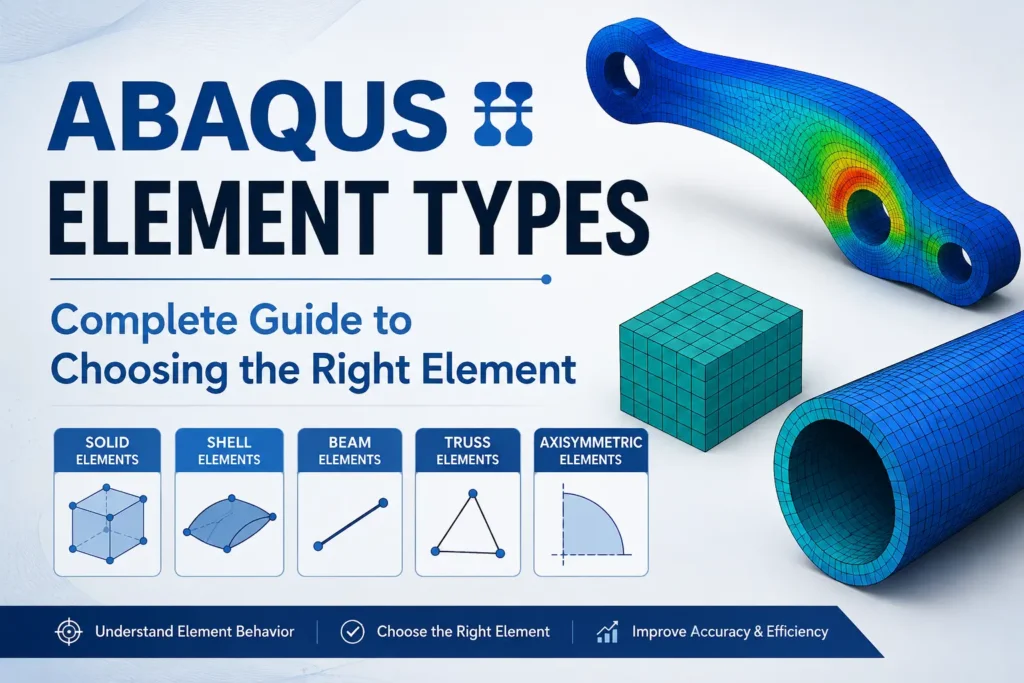
Choosing the wrong Abaqus element type can lead to inaccurate results, poor convergence, or unnecessary computational cost.
This guide explains the major Abaqus element types, including continuum, shell, beam, truss, membrane, thermal, and coupled temperature–displacement elements. You will also learn how Abaqus element names work, when to use reduced or full integration, and how element formulation affects accuracy and computational performance.
Most importantly, this guide shows you how to choose the right Abaqus element for your analysis , whether you are modeling structural, thermal, nonlinear, dynamic, or coupled problems.
Engineering focus: Element selection should follow the physics of the problem, the expected deformation mode, and the required accuracy – not simply the geometry of the model.
1. Abaqus Element Types: Comparison & Selection Guide
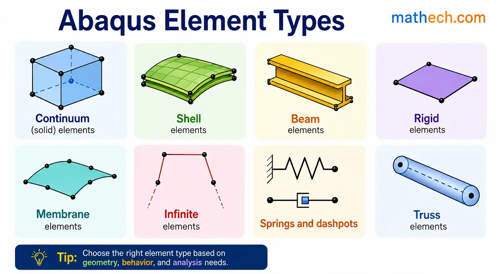
Choosing the right Abaqus element is critical for obtaining accurate, stable, and computationally efficient finite element analysis results. Use this comparison table to select an element based on geometry, dimensionality, material behavior, loading, and analysis requirements.
| Abaqus Element | Family | Dimension | Nodes | Integration | Typical Analysis | Best For | Key Advantage | Main Limitation | Recommendation |
|---|---|---|---|---|---|---|---|---|---|
3D SOLID / CONTINUUM ELEMENTS | |||||||||
| C3D8R 8-node linear brick, reduced integration | Solid | 3D | 8 | Reduced |
Static Nonlinear Dynamic | General 3D structural analysis, plasticity, contact and large deformation. | Excellent balance of accuracy, speed and computational cost. | Requires attention to hourglass behavior and mesh quality. | ★ Recommended |
| C3D8 8-node linear brick, full integration | Solid | 3D | 8 | Full |
Static Nonlinear | Problems where full integration is desirable. | No reduced-integration hourglass modes. | Higher computational cost and possible locking in some cases. | Good |
| C3D8I 8-node brick with incompatible modes | Solid | 3D | 8 | Full |
Structural Bending | Bending-dominated solid structures. | Improved bending behavior in suitable applications. | Not a universal replacement for C3D8R. | Specialized |
| C3D20 20-node quadratic brick | Solid | 3D | 20 | Full |
Structural Nonlinear | High-accuracy models with smooth geometry and stress fields. | Higher-order interpolation provides excellent accuracy. | Higher computational cost. | Advanced |
| C3D20R 20-node quadratic brick, reduced integration | Solid | 3D | 20 | Reduced |
Structural Nonlinear | High-order 3D models where computational efficiency matters. | Combines quadratic interpolation with reduced integration. | Mesh quality and formulation suitability must be checked. | Advanced |
| C3D10 10-node quadratic tetrahedron | Solid | 3D | 10 | Quadratic | Structural | Complex geometries requiring tetrahedral meshing. | Easier meshing of complex geometries. | Can require more elements than an efficient hex mesh. | Good |
SHELL ELEMENTS | |||||||||
| S4R 4-node reduced-integration shell | Shell | 2D surface | 4 | Reduced |
Static Nonlinear Dynamic | Thin plates, sheet metal, panels and thin-walled structures. | Highly efficient for large shell structures. | Requires appropriate thickness, orientation and mesh quality. | ★ Recommended |
| S4 4-node fully integrated shell | Shell | 2D surface | 4 | Full | Structural | Shell models where full integration is preferred. | Avoids reduced-integration hourglass modes. | Generally more computationally expensive than S4R. | Good |
| S8R 8-node quadratic shell | Shell | 2D surface | 8 | Reduced | Structural | Curved shell geometry and higher-accuracy shell models. | Higher-order interpolation can improve representation of geometry. | Higher computational cost. | Advanced |
BEAM & TRUSS ELEMENTS | |||||||||
| B31 2-node 3D beam | Beam | 1D | 2 | Beam formulation |
Static Nonlinear Dynamic | Slender beams, frames and structural members. | Extremely efficient for long slender structures such as 2d continues beam. | Does not represent detailed 3D cross-sectional behavior. | ★ Recommended |
| B32 3-node quadratic beam | Beam | 1D | 3 | Beam formulation | Structural | Curved beams and problems where quadratic interpolation is beneficial. | Improved representation of curved beam behavior. | Often unnecessary for simple straight beams. | Specialized |
| T3D2 2-node 3D truss | Truss | 1D | 2 | Truss formulation |
Static Dynamic | Axial tension and compression members. | Very low computational cost. | Does not represent beam bending stiffness. | ★ Recommended |
CONTINUUM SHELL ELEMENTS | |||||||||
| SC8R 8-node continuum shell | Continuum Shell | 3D | 8 | Reduced |
Nonlinear Structural | Thin structures requiring continuum-shell behavior. | Combines useful aspects of solid and shell modeling. | Requires careful attention to orientation and thickness. | Advanced |
COHESIVE / INTERFACE ELEMENTS | |||||||||
| COH3D8 8-node 3D cohesive element | Cohesive | 3D | 8 | Cohesive |
Damage Debonding Fracture | Adhesive layers, interfaces, delamination and debonding. | Explicitly represents interface stiffness and damage. | Requires appropriate cohesive material parameters. | ★ Recommended |
THERMAL & COUPLED ELEMENTS | |||||||||
| DC3D8 8-node 3D heat-transfer element | Thermal | 3D | 8 | Thermal | Heat Transfer | 3D steady-state and transient heat-transfer simulations. | Efficient for 3D thermal models. | Does not directly provide a structural displacement solution. | ★ Recommended |
| C3D8T Coupled temperature-displacement element | Coupled | 3D | 8 | Coupled | Thermal-Mechanical | Problems requiring simultaneous thermal and mechanical response such as Welding simulation. | Solves temperature and displacement degrees of freedom together. | Should only be used when coupled physics are appropriate. | Advanced |
Element selection should always be verified through mesh sensitivity studies, convergence checks, and comparison with analytical, experimental, or benchmark results. A recommended element is a starting point- not a substitute for model verification.
2. How to Choose the Right Abaqus Element
Use the following decision guide to select an appropriate Abaqus element based on the geometry and physics of your finite element model.
Is the structure 3D?
For general three-dimensional structural models, start by considering continuum solid elements such as C3D8R or higher-order alternatives.
C3D8RIs the structure thin-walled?
If thickness is small compared with the other dimensions, shell elements can provide a much more efficient representation.
S4RIs it a slender structural member?
Use beam elements when the component can be represented by a centerline and cross-sectional properties.
B31Does it carry mainly axial load?
Truss elements are appropriate when bending stiffness is not part of the physical behavior being modeled.
T3D2Is there an interface or adhesive layer?
Cohesive elements can explicitly represent interface stiffness, damage initiation and degradation.
COH3D8Is heat transfer the primary physics?
Use dedicated thermal elements for heat-transfer simulations or coupled elements when thermal and mechanical fields interact.
DC3D8 / C3D8T3. Understanding Abaqus Element Naming Conventions
Abaqus element names (e.g., C3D8R, S4R) follow a consistent code that encodes shape, dimensionality, node count, formulation, and behavior. Once you know the logic, you can instantly identify an element’s key features.
Most Basic Abaqus Element Naming Formats
Most Abaqus element types follow a systematic naming convention. Understanding this format helps you identify the element family, dimensionality, number of nodes, and formulation directly from its name.
A simplified representation of the naming convention is:
For example, S4R can be interpreted as follows:
Another common example is C3D8R:
| Code Part | Meaning |
|---|---|
C | Continuum — solid element family |
3D | Three-dimensional element |
8 | 8 nodes per element |
R | Reduced integration formulation |
C3D8R is an 8-node, three-dimensional continuum element
with reduced integration. It is commonly used for 3D structural
simulations in Abaqus.This naming system helps you quickly recognize many Abaqus element types, including solid, shell, beam, truss, membrane, and cohesive elements. However, not every Abaqus element name follows this simplified pattern exactly, so always check the specific element formulation and analysis procedure before selecting an element for your FEA model.
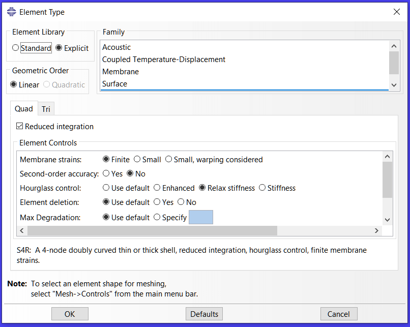
Common Element Families in Abaqus
Here is a Video about Types of Element in Abaqus: (Element Family in Abaqus)
| Prefix | Element Family | Description |
|---|---|---|
| C | Continuum | Three-dimensional solid elements used for structural, stress, deformation, and thermal analysis. |
| S | Shell | Shell elements for thin- and moderately thick-walled structures where the thickness is small relative to the other dimensions. |
| M | Membrane | Two-dimensional elements designed primarily for in-plane, tension-dominated behavior with negligible bending stiffness. |
| B | Beam | One-dimensional structural elements for modeling slender members with bending, axial, and, depending on the formulation, torsional behavior. |
| T | Truss | One-dimensional elements that primarily carry axial tension or compression and do not represent beam bending behavior. |
| COH | Cohesive | Elements for modeling interfaces, adhesive layers, debonding, fracture, and delamination between connected materials. |
| DC | Heat Transfer | Heat-transfer elements used to model temperature fields in thermal analysis, including transient conduction problems. |
Integration and Formulation Codes in Abaqus
Abaqus element names often include letters that identify the integration scheme or element formulation. Understanding these codes helps you select an appropriate Abaqus element type for structural, nonlinear, contact, and coupled finite element analysis.
| Code | Description |
|---|---|
R | Reduced integration — uses fewer integration points, which can reduce computational cost. Reduced-integration elements require attention to hourglass modes and mesh quality. |
I | Incompatible modes — enriches the element formulation to improve its performance in problems involving bending and certain deformation patterns. |
H | Hybrid formulation — introduces additional variables and is particularly useful for nearly incompressible materials such as rubber and other hyperelastic materials. |
P | Pore pressure formulation — used in coupled stress–pore pressure analyses for porous materials and fluid–solid interaction problems. |
AX | Axisymmetric designation — identifies elements intended for axisymmetric models, where the geometry and loading are represented using a two-dimensional cross-section about an axis of revolution. |
Example Interpretations of Abaqus Element Names
The following examples show how the different parts of an Abaqus element name communicate its geometry, dimensionality, node count, and formulation.
| Element | Interpretation |
|---|---|
C3D8 | 3D solid, 8-node brick element with full integration. |
C3D8R | 3D solid, 8-node brick element with reduced integration. |
S4R | 4-node shell element with reduced integration. |
B31 | 2-node beam element using a linear beam interpolation formulation. |
CAX4H | 4-node axisymmetric hybrid element for suitable nearly incompressible axisymmetric analyses. |
Choosing the Right Abaqus Element
Element selection should depend on the physics of the problem, material behavior, deformation mode, mesh quality, and analysis procedure. The following rules provide a useful starting point, but they should be verified through appropriate model validation and mesh convergence studies.
C3D8R identifies a
three-dimensional continuum element with eight nodes and reduced
integration. The complete element formulation, material behavior,
mesh quality, loading, contact conditions, and Abaqus analysis
procedure must all be considered when selecting an element.💡 Need expert support choosing the right Abaqus element type?
Whether you’re facing convergence problems, implementing advanced material models, writing UMAT/VUMAT subroutines, or validating complex finite element analyses, Our team at Mathech Consulting helps you select, validate, and optimize elements for your simulations.
4. Continuum (Solid) Elements: For 3D Bulk Structures
Continuous elements – also known as solid elements – are the basis of most 3D simulations in Abaqus. They represent materials with significant thickness in all directions and capture the full 3D stress and strain states. These elements are used in the simulation of mechanical parts, assemblies, and assemblies where deformation occurs throughout the volume, not just the surface.
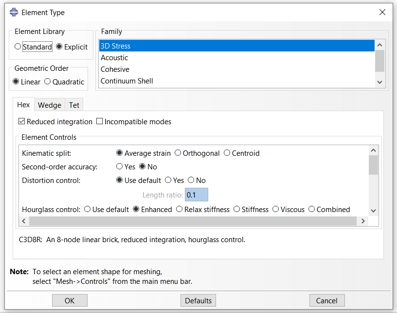
Purpose and Application of Continuum Solid Elements
Continuum elements, also called solid elements, are used to model the three-dimensional behavior of bulk materials and components in Abaqus. They are particularly useful when the structure develops significant stress or deformation through its thickness or in multiple directions.
In finite element analysis (FEA), continuum elements can represent complex three-dimensional stress states, including tension, compression, torsion, contact, and nonlinear deformation.
Shafts, housings, gears, and other components with complex three-dimensional stress distributions.
Components subjected to combined loading, contact, and localized stress concentrations.
Thick-walled vessels where a three-dimensional stress state must be captured accurately.
Complex components with irregular geometry and non-uniform internal stress distributions.
Common Continuum Element Families in Abaqus
Abaqus provides several continuum element formulations. The choice depends on geometry, mesh quality, deformation behavior, integration scheme, and the requirements of the FEA analysis.
| Element | Description | Nodes | Key Features |
|---|---|---|---|
C3D8 | 3D brick (hexahedral) continuum element | 8 | Full integration; useful when the formulation and mesh are appropriate, although computationally more expensive than reduced-integration alternatives. |
C3D8R | 3D brick (hexahedral) element with reduced integration | 8 | Lower computational cost; requires attention to hourglass behavior and element distortion. |
C3D10 | 3D quadratic tetrahedral element | 10 | Quadratic interpolation makes it useful for complex geometries where generating a high-quality hexahedral mesh is difficult. |
C3D20R | 3D quadratic brick element with reduced integration | 20 | Higher-order interpolation with reduced integration; can provide improved accuracy for suitable meshes and nonlinear problems. |
C3D4 | 3D linear tetrahedral element | 4 | Simple and convenient for complex geometry, but generally less effective for bending-dominated problems than suitable higher-order formulations. |
Integration and Formulation Options
The formulation of a continuum element can strongly affect computational cost, bending behavior, volumetric response, and numerical stability. Common options include reduced integration, hybrid formulations, and incompatible modes.
R: Reduced IntegrationUses fewer integration points and can improve computational efficiency. However, reduced-integration elements require attention to hourglassing, mesh quality, and deformation patterns.
H: Hybrid FormulationDesigned for problems involving nearly incompressible behavior. Hybrid elements are commonly considered for materials such as rubber and hyperelastic materials undergoing large deformation.
I: Incompatible Modes
Adds incompatible deformation modes to improve the behavior
of suitable first-order elements in problems where
bending is important, such as
C3D8I.
Key Modeling Guidelines for Continuum Elements
C3D8R and
C3D20R can provide efficient and accurate
solutions when a good-quality structured mesh is possible.
Element performance depends on the formulation and mesh.
When to Use Continuum Elements in Abaqus
Continuum elements are generally appropriate when the model requires a three-dimensional representation of the material. Consider them when:
- The structure has significant thickness or requires a 3D stress distribution.
- The loading produces complex internal stress and strain fields.
- The analysis requires accurate representation of volumetric deformation.
- The component experiences compression, torsion, contact, hydrostatic pressure, or other three-dimensional loading.
- The geometry cannot be represented adequately using a shell, membrane, beam, or truss idealization.
Learn how to build and mesh a 3D model in Abaqus.
5. Shell Elements: For Thin-Walled Structures
At Mathech Consulting Team, we use shell elements in Abaqus when analyzing thin-walled components where one dimension (thickness) is much smaller than the other two. Shell elements efficiently capture both in-plane and bending behaviors without the high computational cost of full 3D solid models.
They are ideal for plates, sheet-metal parts, pressure vessels, enclosures, and structural panels components where stresses vary primarily across the surface rather than through the volume.
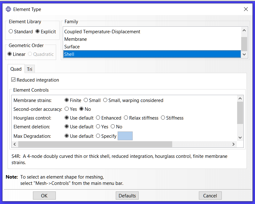
Why Use Shell Elements?
Shell elements model membrane (in-plane) and bending (out-of-plane) responses together.
They are computationally lighter than 3D continuum elements and maintain excellent accuracy for structures with small thickness.
We select shell elements when:
- The thickness-to-length ratio is below 1:10.
- The stress state is dominantly surface-based.
- We need to analyze buckling, vibration, or large deformation in thin parts.
Common Shell Element Types in Abaqus
| Element | Nodes | Type | Key Features |
|---|---|---|---|
| S4 | 4 | Linear quadrilateral | Full integration, general use |
| S4R | 4 | Linear quadrilateral | Reduced integration, faster, widely used |
| S8R | 8 | Quadratic quadrilateral | High accuracy, smoother curvature |
| S3 | 3 | Linear triangular | For irregular geometries or transitions |
| S3R | 3 | Linear triangular reduced | Efficient for complex or curved meshes |
Among these, we often recommend S4R because it balances accuracy and efficiency for most engineering cases.
Integration and Formulation Notes
Reduced Integration (R): Lowers CPU time but can cause hourglassing if mesh quality is poor.
Finite-Membrane Strain Option: Used for large-deformation problems such as forming or bending.
Thickness Definition: Each shell element has a defined thickness, either constant or varying by node.
Offset Option: We can offset the shell’s reference surface from the mid-plane to represent real geometry more accurately.
Modeling Guidelines from Mathech Experience
✅ Mesh Quality Is Critical
Use a uniform, regular mesh. Distorted elements reduce accuracy in bending zones.
✅ Define Correct Thickness
Assign realistic thickness values in the Section Manager. Incorrect values directly affect stiffness and stress results.
✅ Use Quadratic Elements for Curved Surfaces
Elements like S8R handle curvature better and produce smoother stress gradients.
✅ Check Edge Constraints
Shell edges often connect to beams, solids, or other shells. Always verify continuity and compatible boundary conditions.
✅ Prefer Shells Over Solids for Thin Structures
They reduce computation time drastically without losing essential accuracy.
When to Use Shell Elements
Use shell elements in:
- Sheet metal parts
- Thin-walled pressure vessels or tanks
- Aerospace or automotive body panels
- Structural plates, roofs, or enclosures
- Composite laminates (using layered shell sections)
Avoid them when the part has significant 3D stress gradients through the thickness. in those cases, use continuum (solid) elements instead.
6. Beam Elements in Abaqus: Modeling Slender Frameworks Efficiently
At Mathech Consulting Team, we use beam elements in Abaqus to simulate slender structures where one dimension (length) is much greater than the other two (cross-section dimensions).
Beam elements efficiently represent bending, torsion, shear, and axial forces with minimal computational cost that makes them ideal for structural frames, trusses, supports, and mechanical linkages.
Purpose and Application of Beam Elements
Beam elements model the centerline of slender members instead of their full volume.
They are extremely efficient for structures dominated by bending and axial loads, such as:
- Structural frames and bridges
- Support beams or reinforcements
- Shafts and pipelines
- Robotic arms or linkages
- Truss and lattice assemblies
We often use beams when full 3D solid modeling would add unnecessary complexity or computation time.
Common Beam Element Types in Abaqus
| Element | Nodes | Type | Key Features |
|---|---|---|---|
| B31 | 2 | Linear beam | Most commonly used; cubic interpolation of displacement |
| B32 | 3 | Quadratic beam | Higher accuracy for curved geometry |
| B33 | 3 | 3D quadratic beam | Used for advanced 3D frame systems |
| PIPE31 | 2 | Pipe element | Specialized for circular cross-sections |
| FRAME3D | 2 | Legacy element | Used in simple structural analysis |
Cross-Section Definition for Beam Elements
Each beam element requires a defined cross-section that represents its shape and stiffness.
Abaqus provides various section types, including:
- Rectangular, Circular, I-section, T-section, and Pipe
- Composite sections for multi-material beams
- User-defined profiles using the Profile Manager
The section properties directly control the bending stiffness, torsional rigidity, and mass distribution of the element.
Read more about beam element here: The wide range of elements that are available in ABAQUS
Modeling Guidelines for Beam Elements from Mathech Experience
✅ Align the Local Axes Properly
The local coordinate system defines bending directions. Misalignment can cause unrealistic rotations or twisting.
✅ Use Beam Orientations Consistently
Always define the orientation vector for each beam to avoid torsional instability.
✅ Connect Beams Correctly
Ensure nodes at intersections are shared or connected with coupling constraints to transfer forces accurately.
✅ Mesh Density
Use a finer mesh at load application points or joints to capture local bending behavior.
✅ Verify Cross-Section Properties
Incorrect dimensions lead to wrong stiffness or mass calculations.
When to Use Beam Elements
Use beam elements when:
- The structure is slender and behaves mainly through bending or axial loads.
- The cross-section remains constant or varies slowly along the length.
- The interest is in global structural response, not local stress details.
Avoid beams when the structure has thick or complex 3D geometry, local contact, or nonlinear deformation . in such cases, use solid or shell elements instead.
Here is an example of Beam Element Selection: Abaqus CAE file for steel frame structural analysis , including nodal displacements, member forces, and support reactions.
7. Coupled Temperature–Displacement Elements
At Mathech Consulting Team, we use Coupled Temperature–Displacement elements in Abaqus to simulate problems where thermal and mechanical fields interact.
These elements allow us to analyze how temperature changes affect stresses and deformation, and how mechanical work generates heat that is a crucial capability in thermo-mechanical analysis.
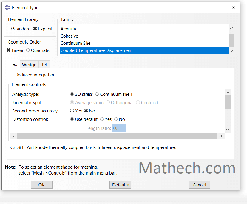
They are essential for accurate modeling in welding, metal forming, electronics, and high-temperature structural applications.
Need Help With Your Welding Analysis in ABAQUS?
Get expert support for Abaqus modeling, FEA, thermal analysis, welding simulation, material modeling, and complex engineering problems.
Tell us about your project, requirements, simulation type, and timeline.
Purpose and Physical Meaning of Coupled Temperature–Displacement Elements
Coupled temperature–displacement elements solve the thermal and mechanical fields together within the same analysis procedure. They provide both temperature degrees of freedom and displacement degrees of freedom.
This allows Abaqus to calculate the evolution of temperature and mechanical response while accounting for the relevant thermo-mechanical interactions defined by the model.
Typical Applications
Coupled temperature–displacement elements are useful in thermo-mechanical simulations where temperature changes influence deformation, stress, or material behavior.
Common Coupled Temperature–Displacement Elements in Abaqus
Abaqus provides coupled temperature–displacement elements for different geometries and formulations. The correct choice depends on dimensionality, interpolation order, integration scheme, and the physics of the simulation.
| Element | Description | Dimensionality | Key Features |
|---|---|---|---|
C3D8T | 8-node brick coupled temperature–displacement element | 3D | First-order coupled thermo-mechanical formulation suitable for appropriate three-dimensional models. |
C3D8RT | 8-node brick coupled temperature–displacement element with reduced integration | 3D | Reduced integration can reduce computational cost; hourglass behavior and mesh quality should be monitored. |
C3D20T | 20-node quadratic brick coupled temperature–displacement element | 3D | Higher-order interpolation can provide improved representation of suitable curved geometries and field gradients. |
C3D20RT | 20-node quadratic brick coupled temperature–displacement element with reduced integration | 3D | Combines quadratic interpolation with reduced integration for suitable thermo-mechanical models. |
CAX4T | 4-node axisymmetric coupled temperature–displacement element | 2D Axisymmetric | Used for appropriate rotationally symmetric thermo-mechanical problems. |
CPE4T | 4-node plane-strain coupled temperature–displacement element | 2D | Suitable for appropriate plane-strain thermo-mechanical models. |
T suffix identifies a
coupled temperature–displacement formulation.
The complete element name also communicates dimensionality,
node count, and other formulation characteristics.Key Modeling Features
Mathech Modeling Guidelines
At Mathech Consulting Team, we focus on matching the element formulation and analysis procedure to the actual physics of the problem. For coupled thermo-mechanical models, we recommend the following practices.
When to Use Coupled Temperature–Displacement Elements
Consider coupled temperature–displacement elements when:
- The temperature field significantly influences mechanical deformation and stress.
- You need to calculate thermal stresses together with the temperature field.
- Heat generation from mechanical processes is important to the thermal response.
- The thermal and mechanical fields need to be solved simultaneously.
- A sequential thermal–mechanical workflow does not adequately represent the required physical interaction.
Coupled Elements for Welding Simulation
Welding simulation is one of the important applications of thermo-mechanical finite element analysis. During welding, the moving heat source produces a highly non-uniform temperature field. The resulting thermal expansion and contraction can generate significant deformation, plastic strain, and residual stress.
In a coupled temperature–displacement analysis, the thermal and mechanical fields are solved together using elements that contain both temperature and displacement degrees of freedom.
For many welding FEA problems, however, the thermal and mechanical fields can also be solved sequentially. The best approach depends on the strength of the thermo-mechanical coupling and the required level of physical fidelity.
Common Coupled Elements for Welding Models
C3D8T
8-node linear coupled temperature–displacement
brick element.
C3D8RT
8-node linear coupled temperature–displacement brick
element with reduced integration.
C3D20T
20-node quadratic coupled temperature–displacement
brick element.
C3D20RT
20-node quadratic coupled temperature–displacement
brick element with reduced integration.
For example, a C3D8RT mesh can be used for a suitable three-dimensional welded component when the welding problem requires simultaneous solution of temperature and mechanical response.
Heat Source in Abaqus Welding Simulation
A welding heat source such as a DFLUX-based moving heat source can represent the spatial and temporal distribution of welding energy input.
The resulting temperature history can produce thermal expansion and contraction. When mechanical constraints and temperature-dependent material behavior are included, the model can predict thermal stress, plastic deformation, and residual stress.
When Should You Use Coupled Elements for Welding?
Coupled temperature–displacement elements are most useful when the thermal and mechanical fields need to interact during the same solution. This can be important for strongly coupled thermo-mechanical problems.
However, you should not automatically use coupled elements for every welding simulation. A sequentially coupled thermal-stress analysis is often a more practical approach when the mechanical response does not significantly affect the thermal solution.
Sequential Welding FEA Workflow
| Aspect | Coupled Temperature–Displacement | Sequential Thermal–Mechanical |
|---|---|---|
| Basic approach | Temperature and displacement are solved together in the same analysis. | Thermal and mechanical analyses are performed separately, with the temperature history transferred to the mechanical model. |
| Typical Abaqus elements |
C3D8T, C3D8RT,
C3D20T, and other coupled
temperature–displacement elements. |
Thermal elements such as DC3D8 are used
for the heat-transfer model, followed by appropriate
structural elements such as C3D8R. |
| Temperature calculation | Temperature is calculated directly within the coupled thermo-mechanical analysis. | Temperature is calculated first in a transient heat-transfer analysis. |
| Mechanical response | Displacement and mechanical response are calculated simultaneously with temperature. | The temperature history from the thermal analysis is applied to the subsequent mechanical analysis. |
| Welding heat source | A moving heat source can be applied while solving the coupled thermal and mechanical response. |
A moving heat source, such as a DFLUX
subroutine, is commonly used in the transient thermal model. |
| Residual stress prediction | Can predict thermal stresses and deformation directly within the coupled analysis. | Residual stresses and welding deformation are calculated in the subsequent mechanical analysis using the imported temperature history. |
| Computational cost | Can be computationally demanding because thermal and mechanical degrees of freedom are solved together. | Often provides greater flexibility and can be more practical for complex welding simulations. |
| Modeling flexibility | Useful when strong interaction between thermal and mechanical fields must be captured simultaneously. | Allows the thermal and mechanical models to be developed, calibrated, and modified independently. |
| Common welding application | Strongly coupled thermo-mechanical problems where simultaneous temperature and mechanical response is important. | Welding temperature prediction followed by analysis of thermal deformation and residual stresses. |
| General recommendation | Choose when the physics requires simultaneous coupling between temperature and mechanical response. | A practical choice for many engineering welding FEA workflows, especially when the thermal history can be transferred to a separate mechanical analysis. |
For welding simulation in Abaqus, the appropriate approach depends on the physical coupling, material behavior, computational cost, and objectives of the analysis. For many engineering welding models, a sequential thermal-to-mechanical workflow provides an effective way to predict the welding temperature field, thermal deformation, and residual stresses.
Here is an example of Coupled Temperature–Displacement elements Selection: Abaqus Welding Simulation with DFLUX : Elliptical Heat Source Path
8. Common Element Selection Mistakes and How to Avoid Them
At Mathech Consulting Team, we often help clients troubleshoot Abaqus simulation errors caused by an inappropriate Abaqus element type. Element selection directly affects the accuracy, stability, and computational efficiency of an FEA model.
Even a carefully constructed Abaqus model can produce unreliable results when the element formulation does not match the physics of the problem. For example, the wrong element can contribute to convergence difficulties, excessive stiffness, poor bending behavior, or unnecessary computational cost.
If you are troubleshooting convergence problems, see our guide to checking Abaqus element types and section assignments .
Using Solid Elements for Thin Structures
Modeling thin plates or shells entirely with 3D continuum elements such as C3D8 or C3D20 can dramatically increase the number of elements through the thickness. It may also make bending behavior more difficult to capture efficiently.
- Use appropriate shell elements such as S4R or S8R for thin or moderately thick structures.
- If a solid representation is required, use sufficient elements through the thickness to resolve the stress gradient.
- Compare solid and shell results when both idealizations are physically appropriate.
Using Tetrahedral Elements for Simple Geometry
Tetrahedral elements such as C3D4 and C3D10 are convenient for complex geometries, but using them unnecessarily can result in a less efficient mesh. Linear tetrahedral elements can be particularly problematic in bending-dominated applications.
- Use suitable hexahedral elements when geometry and meshing strategy allow.
- When tetrahedral elements are necessary, consider quadratic elements such as C3D10 for applications where their formulation is appropriate.
- Check element distortion and refine regions with strong stress or strain gradients.
Mixing Incompatible Element Types
Combining elements with different dimensionalities or formulations, such as solid, shell, and beam elements, without an appropriate connection strategy can produce incorrect load transfer or unrealistic interface behavior.
- Use appropriate tie constraints, coupling constraints, connector elements, or other interface methods when required.
- Ensure that forces and moments are transferred correctly between dissimilar element formulations.
- Avoid connecting beam and solid regions directly without considering the required interface kinematics.
Ignoring Reduced Integration and Hourglassing
Reduced-integration elements can reduce computational cost, but they may exhibit non-physical zero-energy deformation modes known as hourglassing under unsuitable conditions.
Ignoring hourglass behavior can make the deformation field look plausible while the underlying solution is unreliable.
- Monitor hourglass-related energy and deformation behavior in the Abaqus results.
- Improve mesh quality and refinement where necessary.
- For bending-dominated problems, consider a formulation better suited to the problem, such as an appropriate full-integration or incompatible-mode element.
Using Linear Elements in Curved or Contact Regions
Using low-order elements in highly curved geometry or contact regions can require a very fine mesh to represent geometry and field gradients accurately. Poor mesh resolution can lead to inaccurate contact pressure or stress distributions.
- Consider quadratic elements where their formulation is appropriate for the geometry and analysis.
- Refine the mesh gradually around contact interfaces, fillets, and regions with high stress gradients.
- Maintain good element quality rather than relying only on increasing element count.
Neglecting Temperature–Displacement Coupling in Thermal Problems
Thermal and mechanical fields do not always need to be solved simultaneously. However, treating a strongly coupled thermo-mechanical problem as two completely independent analyses can omit important interactions between temperature and deformation.
- Determine whether the problem requires coupled temperature–displacement elements such as C3D8T or C3D20T.
- Define realistic temperature-dependent material properties when required.
- Use transient thermal analysis when the heating and cooling history is important.
- Consider a sequential thermal-mechanical workflow when simultaneous coupling is not required.
Over-Refining the Mesh Without Justification
An excessively fine mesh can increase CPU time, memory requirements, and iteration time without producing meaningful improvements in the quantities of interest. More elements do not automatically mean more accurate results.
- Perform mesh convergence studies and refine the model based on measurable changes in key results.
- Use local mesh controls around holes, fillets, contacts, welds, and strong stress or temperature gradients.
- Compare engineering quantities such as displacement, reaction forces, stress, strain, and relevant energy measures rather than judging mesh quality only by visual smoothness.
9. Conclusion: Building a Reliable Modeling Foundation
At Mathech Consulting Team, we believe that element selection is the foundation of every reliable Abaqus model.
The accuracy, stability, and computational efficiency of your simulation all depend on how well the chosen element type reflects the true physics of your problem.
A well-structured model begins with understanding how each element family behaves – solids for 3D stress fields, shells for thin-walled components, beams for slender structures, and membranes or cohesive elements for specialized interfaces.
Each choice carries assumptions about geometry, deformation, and load transfer. Ignoring these assumptions often leads to misleading results, even when convergence appears successful.
10. Frequently Asked Questions (FAQ) – Element Types in Abaqus
Abaqus provides several element families including solid (continuum), shell, beam, truss, membrane, and coupled temperature–displacement elements. Each family is designed for specific geometry types and deformation behaviors. Selecting the correct one ensures accuracy and convergence in simulations.
Choose solid elements for 3D parts with significant thickness, shell elements for thin-walled structures, and beam elements for slender members. The decision depends on geometry, stress distribution, and computational efficiency. At Mathech, we help clients identify the best option for each project.
Incorrect element selection can cause unrealistic stiffness, locking, or convergence failure. For example, using solid elements for thin parts can lead to shear locking. Matching the element type to the real physical behavior of the structure prevents such issues and ensures accurate results.
These elements are used in thermomechanical simulations where heat transfer affects deformation or stress. Abaqus simultaneously solves temperature and displacement fields, making these elements essential for processes like welding, thermal expansion, or heat treatment analysis.
Review geometry thickness, aspect ratios, and loading type before assigning elements. Use reduced integration when possible, avoid excessive mesh distortion, and verify results through convergence testing. Consulting experts like the Mathech team ensures your model setup is physically and numerically sound.
Need Help Selecting the Right Element for Your Model?
Whether you’re facing convergence problems, implementing advanced material models, writing UMAT/VUMAT subroutines, or validating complex finite element analyses, our Abaqus specialists can help you obtain accurate and reliable results. Choosing the wrong element can derail your project. The FEA experts at Mathech can review your model and recommend the most efficient and accurate element types for your specific application, saving you time and ensuring reliability.
11. More Resources on Abaqus Element Types
Want to learn more about Abaqus element formulations, element selection, integration schemes, mesh quality, and finite element modeling? Explore these additional resources for deeper technical guidance.
Abaqus Documentation
Explore the official Abaqus documentation for element formulations, analysis procedures, material models, contact, meshing, and finite element modeling.
Read Documentation →Abaqus Element Library
Learn how Abaqus element families are organized, including solid, shell, beam, truss, cohesive, thermal, and coupled-field elements.
Explore Element Types →Abaqus Meshing and Element Selection
Understand how geometry, mesh topology, element formulation, distortion, and mesh density affect the quality of an Abaqus simulation.
Learn About Meshing →Finite Element Formulation
Review the fundamentals behind interpolation functions, numerical integration, element stiffness, locking, convergence, and finite element formulations.
Read More →Abaqus Nonlinear Finite Element Analysis
Learn how element selection interacts with material nonlinearity, geometric nonlinearity, contact, large deformation, and nonlinear solution procedures.
Explore Nonlinear Analysis →Abaqus Tutorials and Guides
Browse more Mathech tutorials covering Abaqus modeling, meshing, material definitions, boundary conditions, nonlinear analysis, and simulation workflows.
Explore Mathech Tutorials →




Completely I share your opinion. In it something is also to me it seems it is excellent idea. I agree with you.
——