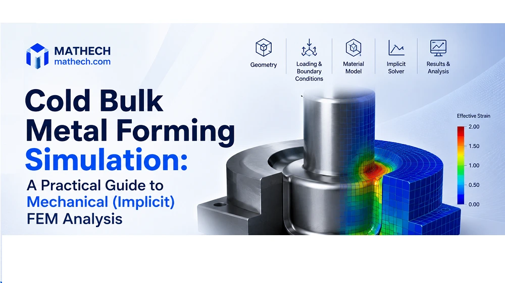
Cold bulk metal forming is a widely used manufacturing process for producing strong, precise metal components. Unlike hot forming, it shapes metal below its recrystallization temperature, typically at room temperature. This process improves mechanical properties through strain hardening, but it also creates complex stress and deformation patterns that require careful engineering analysis.
In this practical guide, you will learn how to perform a cold bulk metal forming simulation using a simple cylindrical compression (upsetting) test. The tutorial covers the complete workflow, including geometry creation, material definition, contact setup, boundary conditions, meshing, simulation, and result interpretation.
1. What Is Cold Bulk Metal Forming?
Cold bulk metal forming is a manufacturing process that shapes metal below its recrystallization temperature. High mechanical forces deform it permanently.
Common cold forming processes include:
- Cold forging
- Upsetting
- Extrusion
- Compression
During these processes, the metal undergoes plastic deformation, meaning it keeps its new shape after the load is removed. Because of this, an accurate stress-strain curve is essential for reliable FEM simulation results.
2. Why Use Mechanical (Implicit) FEM Simulation?
Mechanical (Implicit) FEM analysis is the preferred method for slow, quasi-static cold forming processes.
It is ideal when:
- The forming process is slow.
- Accurate stress and strain results are required.
- Numerical stability is more important than simulation speed.
- The goal is to predict deformation and forming forces.
In Abaqus, this analysis uses the Standard (Implicit) solver. Unlike the Explicit solver, which is mainly used for impacts and crash analysis, the Implicit solver provides accurate predictions of:
- Material flow
- Stress distribution
- Plastic deformation
- Forming forces
- Final part shape
Need Expert Abaqus Simulation Support?
Whether you’re facing convergence problems, implementing advanced material models, writing UMAT/VUMAT subroutines, or validating complex finite element analyses, our Abaqus specialists can help you obtain accurate and reliable results.
3. Step-by-Step Cold Bulk Metal Forming Simulation
Step 1. Define the Forming Process
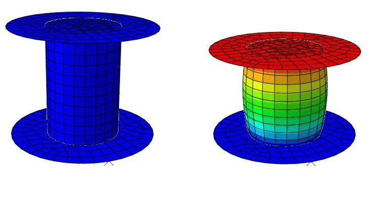
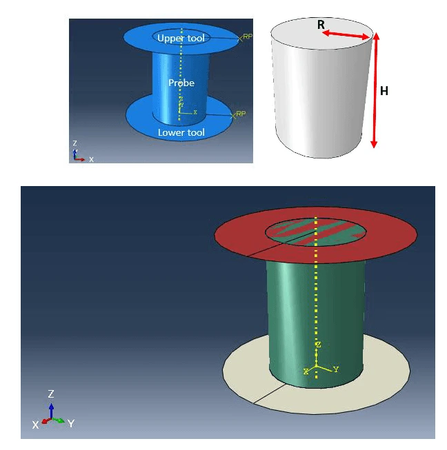
The model consists of a cylindrical metal billet compressed between two flat rigid dies.
- The lower die remains fixed.
- The upper die moves downward.
- The billet is compressed until the required deformation is reached (for example, a 20% reduction in height).
This setup represents a typical cold upsetting or forging operation.
Step 2. Define Material Properties
Material data has the greatest impact on simulation accuracy.
Typical material properties include:
- Density
- Young’s modulus
- Poisson’s ratio
- Plastic stress-strain (flow) curve
The plastic flow curve describes how the material hardens during deformation and should be obtained from experimental tensile or compression tests whenever possible.
| Units SI | Model in m | Model in mm |
| Density | 7950 𝑘𝑔/𝑚3 | 7.95𝐸−9 𝑡𝑜𝑛𝑛𝑒/𝑚𝑚3 |
| Young’s module | 210𝐸9 𝑃𝑎 | 210000 𝑀𝑃𝑎 |
| Poisson’s coefficient | 0.3 | 0.3 |
Important: Always use a consistent unit system. Incorrect units are one of the most common causes of simulation errors.
See more Abaqus Units Tutorial: How to Set and Manage Units Correctly
Step 3. Create the Geometry
The model normally contains three parts:
- A deformable cylindrical billet
- A rigid upper die
- A rigid lower die
Each rigid die requires a reference point, where loads and boundary conditions are applied.
Finally, assemble the parts so the billet is centered between the two dies.
Step 4. Create the Analysis Step
Use a Static, General analysis step.
This step is suitable for quasi-static cold forming, where inertia effects are very small and the focus is on stress, strain, and deformation.
Step 5. Apply Boundary Conditions
Typical boundary conditions are:
- Fix the lower die in all directions.
- Apply a downward displacement to the upper die.
This loading creates plastic deformation inside the billet and allows the calculation of forming forces.
In the example, the lower tool is to be locked in all degrees of freedom. Therefore, the “Encaster” option is set to the lower tool reference point in Step-1->BC-1->Mechanical ->Symmetry/Antisymmetry/Encaster.
The upper tool moves by 30mm, deforming the sample by 20% from its height
Step 6. Define Contact
Contact between the billet and dies must be defined correctly.
A typical setup includes:
- General contact
- Penalty friction
- Friction coefficient around 0.3 (adjust according to experimental data)
Friction strongly influences:
- Material flow
- Barreling effect
- Forming force
- Stress distribution
Step 7. Mesh the Model
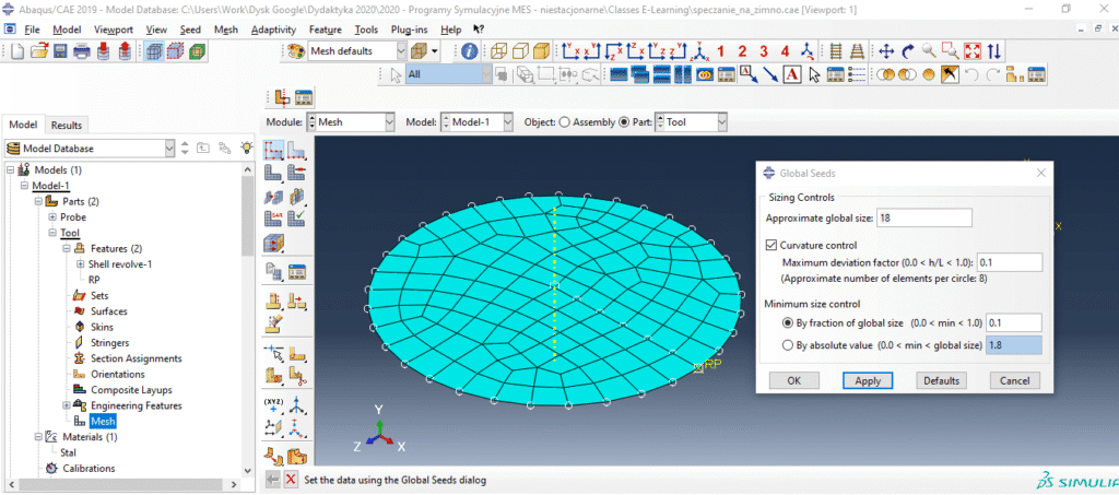
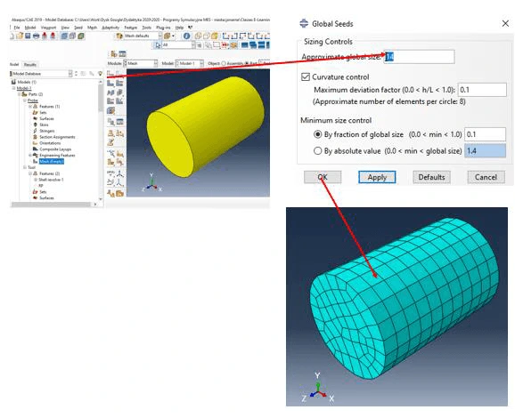
Generate the finite element mesh before running the analysis.
Good practice includes:
- Use a finer mesh for the deformable billet.
- Use a coarser mesh for rigid dies.
- Balance accuracy with computation time.
A quality mesh improves stress and strain predictions.
Step 8. Run the Simulation
After completing the model:
- Check the geometry.
- Verify material properties.
- Review boundary conditions.
- Confirm contact interactions.
- Submit the job.
Monitor the analysis to ensure the solution converges successfully.
Step 9. Review the Results
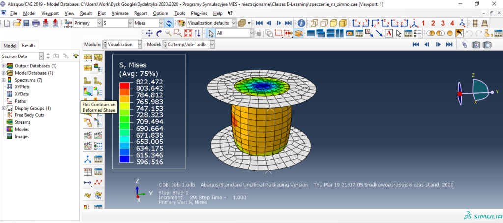
After the simulation finishes, evaluate the results using contour plots.
If you click the right mouse button on the “Job-1” and enable the Monitor option, you can see the numerical values or the message “Complete” is written, it means that ABAQUS counted the simulation correctly.
Errors or warnings may appear then “Error” message will appear then you need to see in the logs what the problem is and correct it according to the above instruction.
Check Abaqus Convergence Issues if you see any Errors
If everything calculated correctly you can go to the results analysis by right clicking on “Job-1” and “Results”. Clicking “Plot Contours on Defromed Shape” allows you to view the distributions of different calculated values such as stresses, deformations and displacements
Typical outputs include:
- Von Mises stress
- Plastic strain
- Displacement
- Material flow
- Reaction force
- Final billet shape
These results help engineers:
- Validate die designs
- Estimate forming loads
- Improve product quality
- Reduce manufacturing costs
- Minimize physical testing
4. Tips for Accurate Cold Forming Simulation
To achieve reliable results:
- Use consistent units throughout the model.
- Use accurate material data, especially the plastic stress-strain curve.
- Define realistic friction conditions between the billet and dies.
- Choose an appropriate mesh density for the required level of accuracy.
- Use the Implicit (Standard) solver for slow, quasi-static cold forming processes.
Following these best practices improves simulation accuracy and helps predict real manufacturing behavior before production begins.
5. Frequently Asked Questions (FAQ) – Cold Bulk Metal Forming Simulation
Cold bulk metal forming is a manufacturing process, such as upsetting, forging, extrusion, or compression, that plastically reshapes a metal billet at room temperature. Because it happens below the material’s recrystallization temperature, it increases yield strength through strain hardening while producing high-strength parts with excellent surface finish and minimal material waste.
Cold forming processes are quasi-static, meaning deformation happens relatively slowly and inertial effects are negligible. A mechanical, implicit solver (such as ABAQUS Standard) solves the equilibrium equations directly, giving accurate stress, strain, and reaction force results. Explicit solvers are generally reserved for high-speed events like impact or crash simulations, where dynamic effects dominate the response.
A reliable model needs density, Young’s modulus, and Poisson’s ratio to define elastic behavior, plus a plastic stress-strain (flow) curve to capture how the material hardens once it deforms beyond yield. This flow curve is usually derived from real tensile or compression test data rather than assumed values, since it has a major influence on simulation accuracy.
Friction, typically modeled with a penalty contact formulation and a defined coefficient of friction, strongly influences material flow, barreling of the compressed sample, and the total forming force needed. Since friction conditions vary by lubrication, tool finish, and material, this parameter should be validated against real process data whenever possible rather than left at a generic default.
Unit inconsistency is one of the most frequent errors. If a model is built in millimeters, density, modulus, and other material properties must be converted into matching units (for example, tonne/mm³ instead of kg/m³). Mixing unit systems is a leading cause of unrealistic forces, incorrect stiffness, or solver convergence problems in mechanical FEM simulations.
6. Conclusion
Mechanical (Implicit) FEM simulation is an essential tool for analyzing cold bulk metal forming processes. By accurately modeling material properties, tooling, contact interactions, and boundary conditions, engineers can predict forming forces, material flow, stress distribution, and final part geometry before manufacturing begins. This reduces development time, lowers production costs, and minimizes the need for costly physical trials.
Whether you are simulating a simple compression test or a complex multi-stage cold forging process, the same core principles apply. Use a consistent unit system, accurate material data, realistic cotact and friction conditions, and an appropriate finite element mesh. Following these best practices helps produce reliable simulation results and supports better tool design, process optimization, and product quality.